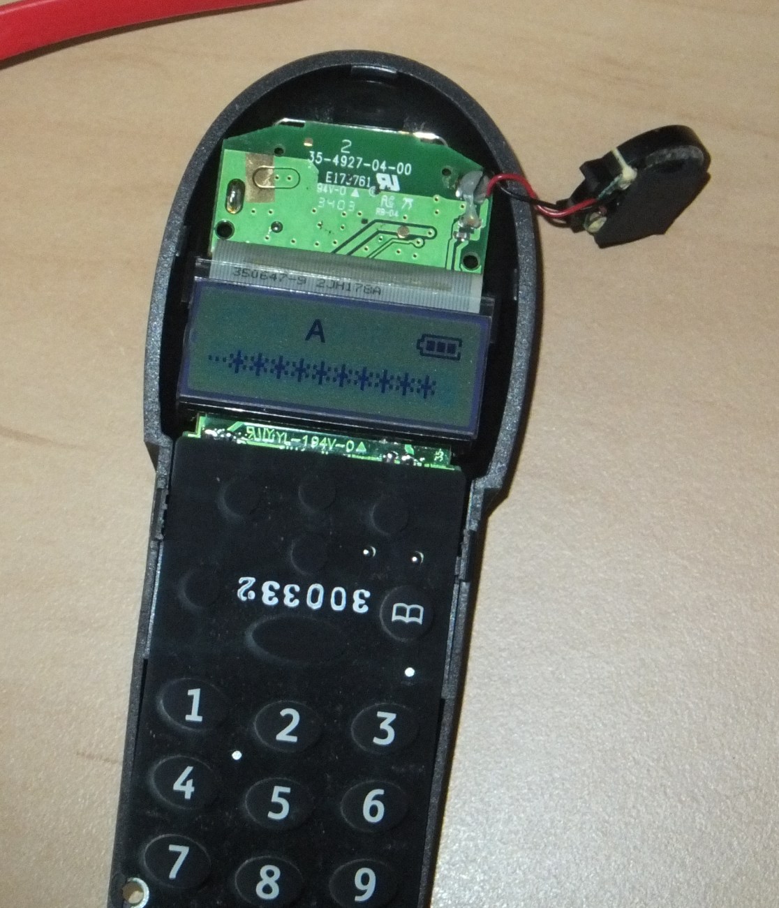
My house phone has an LCD to show numbers and information, but some of the LC segments do not light up making the display useless:-

Display should say FREESTYLE

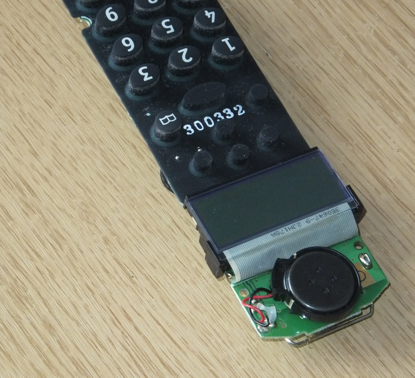
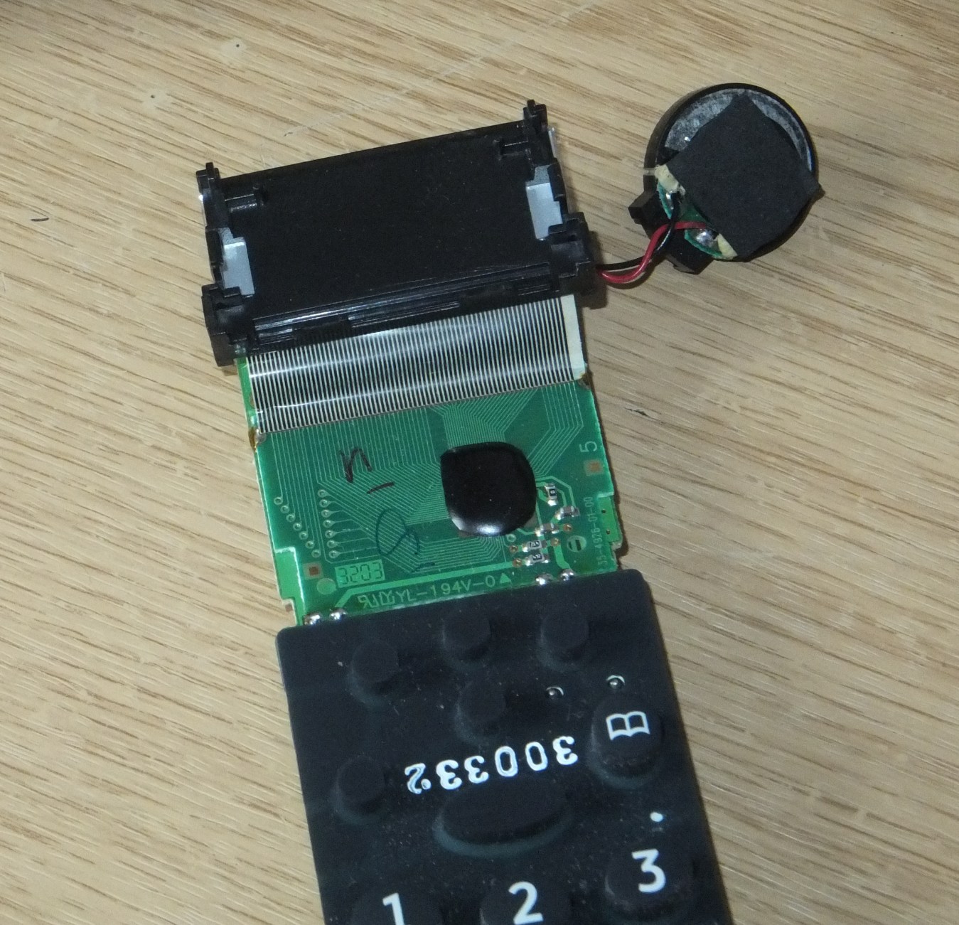
I thought there might be something wrong with the connection between the main board and the display, so I had a look. I was expecting a silicon zebra-stripe connector, which I've seen before, but this one uses a flexible connector that is heat bonded to the main board and the display. WARNING: be gentle with the flexible connector; it turns out the can tear quite easily frown.

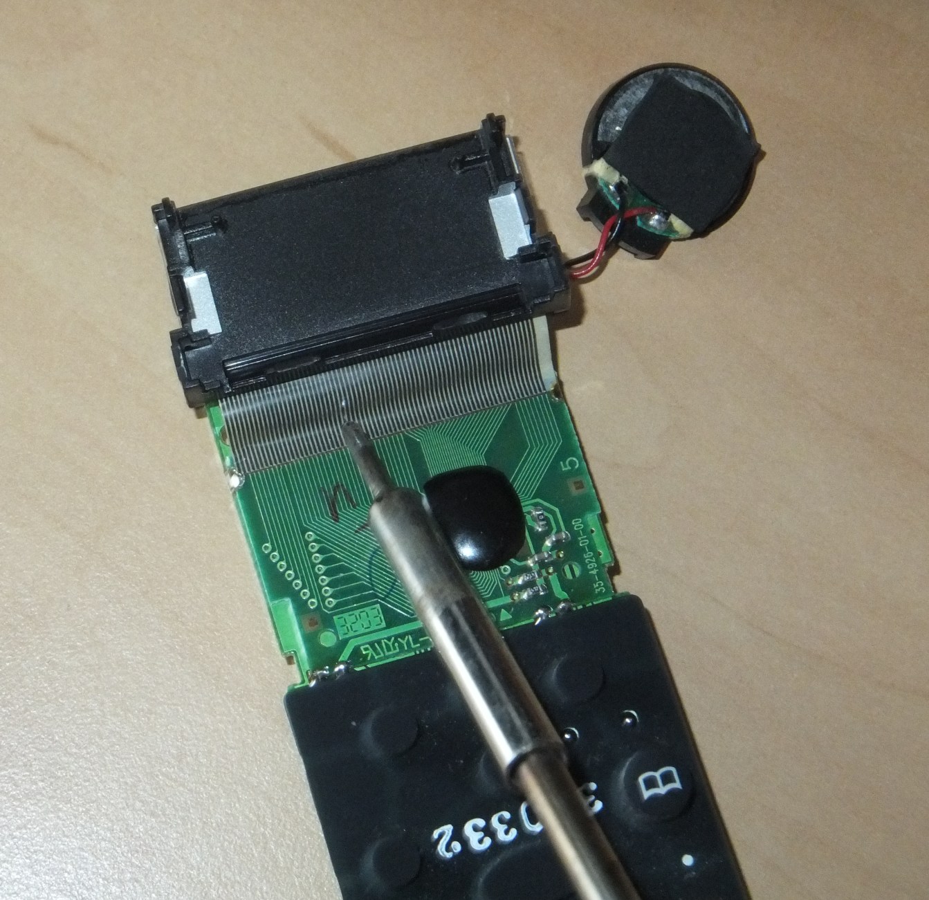
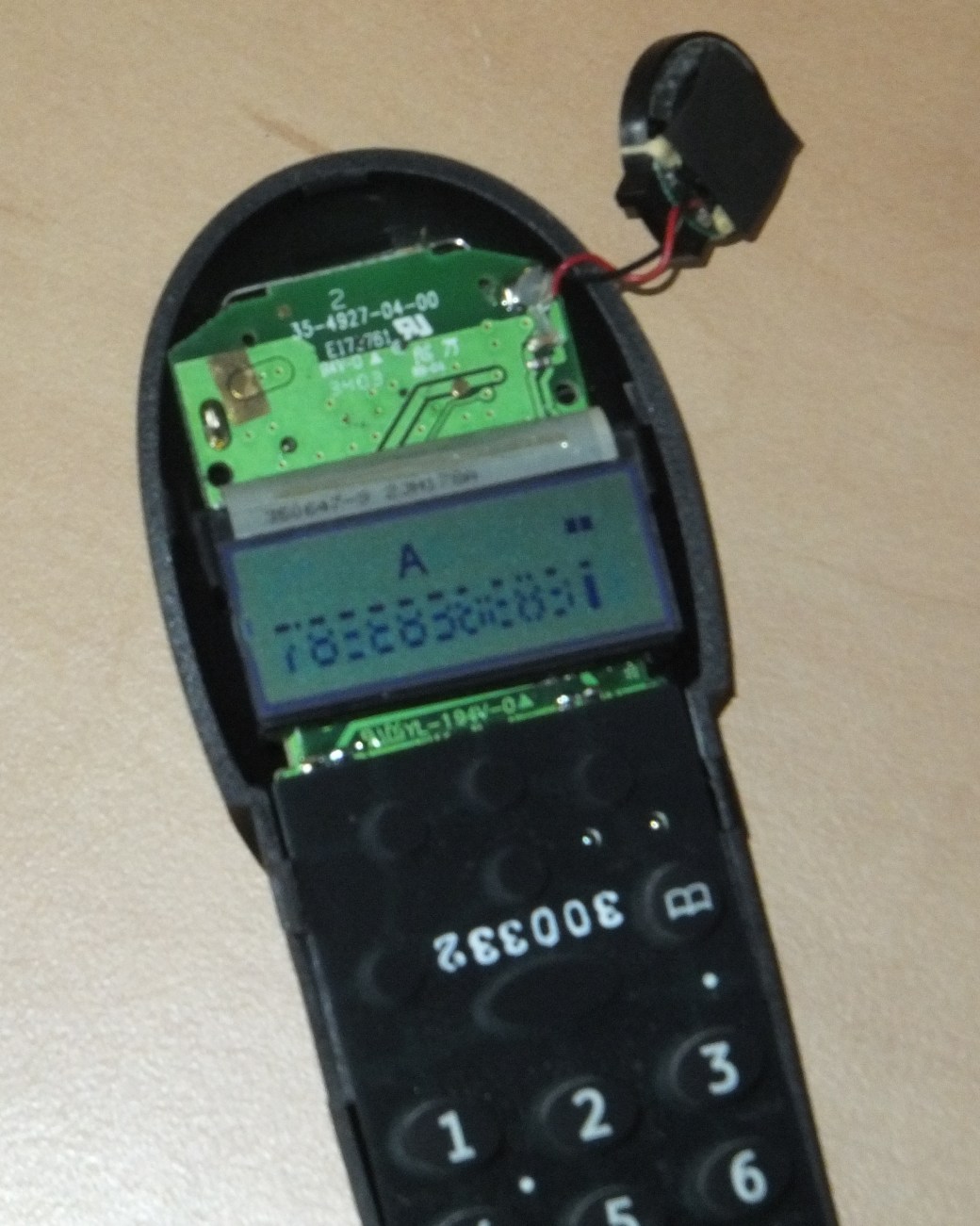
I thought maybe the bonding between the connector and the board had deteriorated causing some of the connections to become disconnected. So I thought I'd try rebonding the connections by using my soldering iron. I set my iron to 200oC and slowly ran the tip along the connector where it is bonded to the board. After the first attempt I noticed some of the LCD segments were back, and after a few more goes, the display was back to normal:-

I bought a cheap 12V 6A PSU off of ebay last year which I use for powering projects that I’m messing around with. It’s appeared to be working fine until a few months ago when it stopped working.

So I cracked it open, as you do, and found that whoever/whatever soldered this thing did a pretty poor job. Many of the solder joings were dull, and the pins from a number of components, including the large capacitor and the devices connected to the heat sinks, had become unsoldered and were basically sitting in free air.

PSU Circuit Bottom PSU Circuit Top

So I resoldered everything and got it working again, and it’s been (apparently) fine since.


I have recently started playing with an electrec microphone with a view to using it with a MSGEQ7 graphic equaliser. I was breadboarding the microphone and simple transistor amplifier to feed in to the MSGEQ7 and was using my scope to view the wave forms, and noticed this continuous pulsing no matter what point in the circuit I tested

DS2_QuickPrint5

I thought at first it’s something caused by the DC filter capacitor, but I looked at other peoples circuits I didn’t notice this pulsing, so I tried replacing components, with no effect. I briefly thought it might be the scope picking up a 50Hz mains hum, but realised the pulse frequency is too high for that.

I then noticed that even when the scope probes aren’t touching my circuit, the pulse was still there, so I though there was something wrong with the scope. I turned off the PSU to power down my project while I tried to work out what was wrong with the scope, and noticed that the pulse went away. I turned the PSU back on and the pulse came back.


TL, DR

The PSU is somehow introducing some high frequency pulse in to something. I don’t know if it’s in to the mains line, or just some EMI – not really sure how to test either of these.


and A number of the componentsre was hardly any solder around a number of components, and both pins on the large capacitor were not soldered

Thought I'd make another word clock with some imporvements. Clicky

I was watching some videos about making PCBs using solder paste and ovens to reflow the solder, and I wondered how easy it would be to remove components in a similar fashion. What to use as the heat source?  A hot-air gun/paint stripper.

I had an old compact flash card reader that's been sitting in a draw for years, so I thought I'd use that as my first victim/experiment.

20 minutes later I have a bunch of random components, which may or may not be of some use at some point (Edit: I found a use for some of the SMD resistors in the other word clock I'm making), but hey – it worked:-

Components removed from PCB

Voila; a bunch of random components. There's some octal flip-flops, resistor arrays, SMD resistors, through-hole transistors, smd transistors and diodes, a couple of large capacitors and other bits and pieces.

Component Haul

The heat gun I have has two settings; I used the low setting, which is about 350 degrees C. The high setting is about 600 degrees.

I clamped the board upright in a vice and found that the larger SMD components just fell off as the solder melted, whereas the smaller components I had to pick off with some tweezers.

This particular board is a 4 layer board and I found that the through hole components took a minute or so of heating before the solder melted all the way through enough for me to pull the components off. I also tried this on an old PS/2 ball mouse PCB, which was just a double sided board, and the through-hole components on that came out much easier.

Only disappointing thing is that SMD capacitors don't have any markings on them, so you don't know what their capacitance is. How easy is it to make a capacitance meter?

I thought I would have a go at making an LED cube.

I had some 4017 decade counters, so I was thinking about making a 10x10x10 RGB cube. From a numver of other LED cubes I've seen, the way that they do it is to provide power to all of the LEDs in every column that contains the LED to be lit, and then ground the plane containing the LEDs to be lit. If I wanted to have a 10x10x10 RGB cube, that would mean I would need 300 lines for the LED anodes, plus 10 for the cathods (assuming common-cathod LEDs).

It occurred to me that maybe you could do it another way; join all of the LED anodes together in a plane, and then ground each column. This way I would only need 30 lines for the anodes, plus 100 for the cathods.

I thought I would try a simple one first using this method; a 3x3x3 mono LED cube. I also thought I'd try some hardware that I haven't used before; an Arduino UNO.

3x3x3 Mono LED Cube

3x3x3

Was bored, so decided to have a go at making a Word Clock.