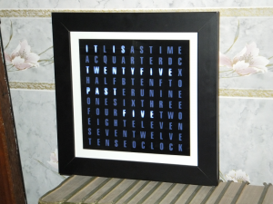
I decided to have a go at making a Word Clock, which, as the name implies, shows the time as words. The face of the clock will contain a grid of letters, and will show the approximate time by highlighting appropriate words within the grid.
Overview
Processor
For the processor I will use a PICAXE 18M2+ as I've used PICAXE before. The chips are cheap (£2) and are easy to program using the free Programming Editor.
Clock
To maintain the time I will use a DS1307 RTC with an external resonator. A better option was the DS3232 which has an internal resonator, but that only appears to be available in a surface mount package, which I've found difficult to build in to a circuit. The DS1307 comes in a simple, fat finger friendly, 8 pin DIP.
LED Drivers
The clock face will contain a grid of 110 letters, 11 letters across by 10 down. Each letter will have a single LED to light it, thus requiring the ability to drive 110 LEDs.
I have gone for the MAX7219 drivers which are designed to drive up to 8 seven segment displays (plus decimal); i.e. a MAX7219 can drive a total of 64 LEDs. So I will need to use two of these.
Case
The clock will be housed in a deep, 10 inch square picture frame. The clock face will consist of a vinyl mask with the letters cut out.
Parts
| DS1307 RTC IC | http://www.techsupplies.co.uk | £2.30 | £3.50 |
| 32.768 kHz resonator | http://www.techsupplies.co.uk | £0.22 | |
| CR2032 battery holder | http://www.techsupplies.co.uk | £0.40 | |
| PICAXE-18M2 microcontroller | http://www.techsupplies.co.uk | £2.00 | |
| MAX7219CNG LED driver (x2) | eBay (it_2002) | £3.90 | £1.35 |
| 5V AC-DC power supply | eBay (megabrokers) | £6.49 | |
| 3mm Ulra Bright White LED (x110) | eBay (bright_components) | £6.14 | £0.99 |
| 10 inch square 40mm deep picture frame | eBay (alanw7865 – Essex Gallery) | £13.00 | £3.00 |
| SPST Momentary push switch (x4) | eBay (ha5ia) | £2.38 | |
| 2.1mm DC power panel mount socket | eBay (donedeal1966) | £0.28 | |
| Royal Blue vellum paper | eBay (lynneduncan) | £0.10 | |
| Resister 1k5 (x2) | |||
| Resister 1k0 (x4) | |||
| Resister 10k0 (x4) | |||
| Resister 18k0 (x2) | |||
| Resister 4k7 (x2) | |||
| 5mm standard red LED | |||
| Capacitor 10uF Electrolytic (x2) | |||
| Vinyl for clock face | http://www.provinylcutz.co.uk/ | £15.00 |
The Build
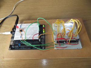
I did some initial testing of the electronics using a breadboard.
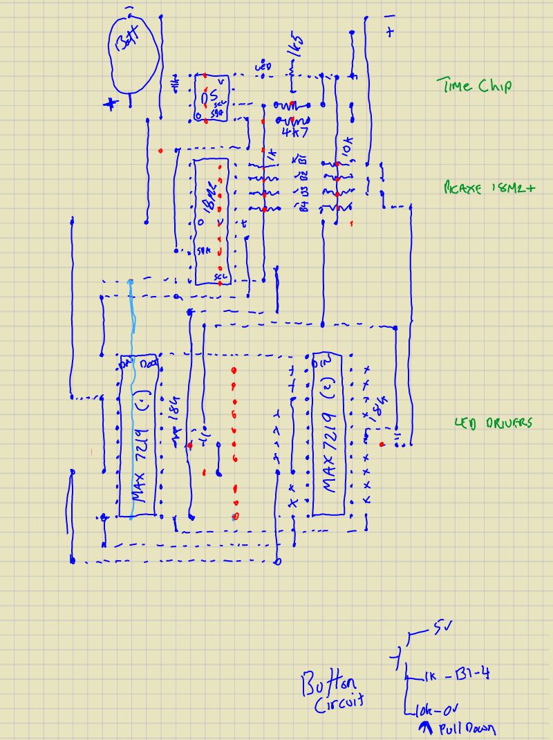
Since I don't have the ability to create proper circuit boards, I will be using strip board. I drew a rough sketch of the circuit layout:-
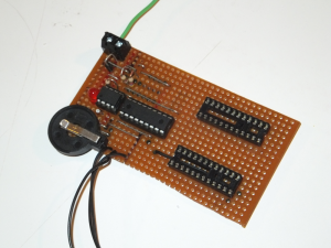
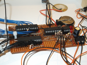
Starting to build the circuit:-
The leads next to the battery are to a socket which is used for programming the 18M2 micro controller.
Originally I placed a diode on the +V line as a way to protect the components if the power was connected incorrectly. However, I found that the ICs seemed to act erratically, so I assumed the diode was causing too much of a voltage drop resulting in the problem, so I took it out and everything worked OK.
The completed circuit:-
The MAX7219 ICs require a 0.33uF electrolytic capacitor on the power lines. Since there wasn't enough room on the top of the board, I soldered a capacitor on the underside of the board directly from the +V pin to the 0V pin.
The bundles of black and blue wires coming from the MAX7219 ICs are the leads for the LEDs.
The black wires between the resistors next to the 18M2 go to the 4 buttons.
Clock face
The clock face will be illuminated by an array of 110 white LED's; one for each letter. The layout of the letters are on a fixed grid; 11 letters across by 10 letters down. The layout I decided on have letters that are 13mm tall, and spaced 12mm (on centre) horizontally, and 20mm (on centre) vertically. The grid is centred within a 250mm (10 inch) square.
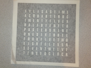
The vinyl template, still with it's backing paper:-
I copied the letter grid from a similar project I saw on MAKE: http://blog.makezine.com/projects/small-word-clock/
The vinyl template has a sticky side and needed to be stuck to a a piece of glass. I decided to stick it to a piece of clear Perspex that I had available. It turned out to be quite difficult to get the vinyl positioned correctly and to remove air bubbles, of which there are still a few. I used the "wet method" to position the vinyl, which involved spraying water on the back of the vinyl and the surface it was going to be fixed to. The water is, apparently, supposed to allow some movement of the vinyl when it is positioned, but I found that as soon as touched the Perspex it became fixed – The vinyl is quite thin, so I didn't want to pull on it too hard to try and lift it again.
I decided to use a piece of thin Perspex, since it's easy to cut and drill for mounting the LED's. Once the clock was built though, an issue became apparent where ambient light from an LED went out through the Perspex and up in to adjacent cells.
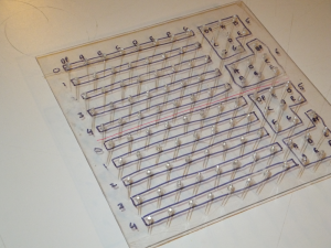
Thin perspex marked with positions of LED's:-
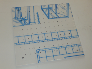
Drilled and LEDs inserted:-
A small drop of superglus was used to hold each LED in place. I also drew in the digit and segment relations from the MAX7219 ICs. One MAX7219 will drive the top 5 rows of the grid, and the other MAX7219 will drive the lower 5 rows.
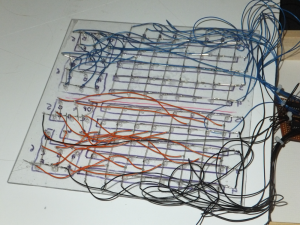
LEDs wired up:-
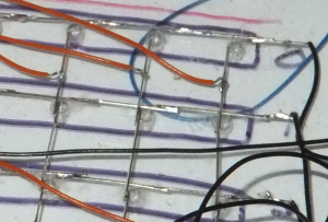
To wire the grid of LEDs, I simply used the legs of the LED's and soldered them to next LED. For each "digit" driven by the MAX7219, I joined all of the cathodes together, and for each "segment" driven by the MAX7219 I joined all of the anodes remembering that one MAX7219 drives the first 5 rows and the other drives the bottom 5 rows. I then just ran wires from an appropriate point in the LED lines to the circuit board.
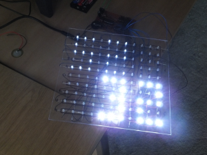
Testing the display:-
Testing the display by showing the time as digits. The first MAX7219, which is driving the top half of the display, is set to about one third brightness, while the second MAX7219 is set to full brightness.
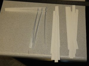
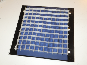
The restrict the amount of light leakage from one letter to the next, I created a grid using cardboard strips. I simply cut a number of card strips the same width, created cuts within each strip at appropriate intervals and made the grid simply by slotting the pieces together:-
I glued small tabs to each corner of the completed cardboard grid, and then used those tabs to tape the grid to the back of the perspex with the vinyl mask. I also inserted a piece of blue vellum paper to provide some colour and diffuse the light from the LED's:-
Completed clock:-
PICAXE Code
Below is the code for the PICAXE:-
#PICAXE 18M2
#terminal off

; Copyright (c) 2013 Marc Symonds.
; Feel free to copy and modify as you wish.

#rem
DS1307 Pins

        +---+
    X1 -|1  |- Vcc
    X2 -|   |- SQW/OUT
+VBatt -|   |- I2C/SCL
    0V -|   |- I2C/SDA
        +---+


PICAXE18-M2 Pins
                               +---+
         Piezo - (Out/In) C.2 -|1  |- C.1 (In/Out) - Button - Mode
                    (Out) C.3 -|   |- C.0 (In/Out) - Button - Set
                     (In) C.4 -|   |- C.7 (In/Out) - Button - Adjust
                     (In) C.5 -|   |- C.6 (In/Out) - Button - Brightness
                          0V - |5  |- Vcc
                 (Out/In) B.0 -|   |- B.7 (In/Out) - MAX7219/DATA
DS1307 - (Out/In/I2C SDA) B.1 -|   |- B.6 (In/Out)
                 (Out/In) B.2 -|   |- B.5 (In/Out) - MAX7219/CLK
  MAX7219/LOAD - (Out/In) B.3 -|9  |- B.4 (In/Out/I2C SCL) - DS1307
                               +---+


Memory:-

00 - 27 - Registers
30 - 36 - Top half buffer.
37 - 43 - Bottom half buffer.
44 - 50 - Top half buffer compare.
51 - 57 - Bottom half buffer compare.

Sending to the MAX7219 is slow, so we only send data where something has changed.


Digit/Segment layout on display (11x10):-

0P 0A 0B 0C 0D 0E 0F 0G 6P 6A 6B
1P 1A 1B 1C 1D 1E 1F 1G 6C 6D 6E
2P 2A 2B 2C 2D 2E 2F 2G 6F 6G 7P      First MAX7219
3P 3A 3B 3C 3D 3E 3F 3G 7A 7B 7C
4P 4A 4B 4C 4D 4E 4F 4G 7D 7E 7F
--------------------------------
0P 0A 0B 0C 0D 0E 0F 0G 6P 6A 6B
1P 1A 1B 1C 1D 1E 1F 1G 6C 6D 6E
2P 2A 2B 2C 2D 2E 2F 2G 6F 6G 7P      Second MAX7219
3P 3A 3B 3C 3D 3E 3F 3G 7A 7B 7C
4P 4A 4B 4C 4D 4E 4F 4G 7D 7E 7F

P = DP.

#endrem


; MAX7219 Pins
symbol MAX7219_LOAD = B.3
symbol MAX7219_DIN = B.7
symbol MAX7219_CLK = B.5

; MAX7219 Registers
symbol MAX7219_NOOP = $00
symbol MAX7219_DIGIT0 = $01
symbol MAX7219_DIGIT1 = $02
symbol MAX7219_DIGIT2 = $03
symbol MAX7219_DIGIT3 = $04
symbol MAX7219_DIGIT4 = $05
symbol MAX7219_DIGIT5 = $06
symbol MAX7219_DIGIT6 = $07
symbol MAX7219_DIGIT7 = $08
symbol MAX7219_DECODE_MODE = $09
symbol MAX7219_INTENSITY = $0A
symbol MAX7219_SCAN_LIMIT = $0B
symbol MAX7219_SHUTDOWN = $0C
symbol MAX7219_TEST_MODE = $0F

; DS1307 Address
symbol DS1307_ADDRESS = %11010000

; DS1307 Registers
symbol DS1307_SECONDS = $00
symbol DS1307_MINUTES = $01
symbol DS1307_HOURS = $02
symbol DS1307_WEEKDAY = $03
symbol DS1307_DAY = $04
symbol DS1307_MONTH = $05
symbol DS1307_YEAR = $06
symbol DS1307_CONTROL = $07
symbol DS1307_RAM = $08 ; to $3F

; DS1307 Bits (assumes b0 used to manipulate values)
symbol DS1307_SECONDS_CH = bit7 ; Clock Halt - high = halt, low = go

symbol DS1307_HOURS_1224 = bit6 ; high = 12 hour, low = 24 hour
symbol DS1307_HOURS_AMPM = bit5 ; high = PM, low = AM (in 12 hour mode)

symbol DS1307_CONTROL_OUT = bit7
symbol DS1307_CONTROL_SQWE = bit4
symbol DS1307_CONTROL_RS1 = bit1
symbol DS1307_CONTROL_RS0 = bit0


; We'll use the DS1307 RAM to store some values in case main power is lost.
symbol DS1307_USR_MODE = DS1307_RAM + $00 ; Display mode
symbol DS1307_USR_BRIGHTNESS = DS1307_RAM + $01 ; Brightness level


; Display data will be buffered in these memory loctations, before being sent to the display (MAX7219).
symbol MEM_DISPLAY_TOP = 30 ' Start of buffer for top half of display.
symbol MEM_DISPLAY_TOP_END = 36 ' End of buffer for top half of display.
symbol MEM_DISPLAY_BOTTOM = 37
symbol MEM_DISPLAY_BOTTOM_END = 43

symbol MEM_DISPLAY_TOP_CMP = 44
symbol MEM_DISPLAY_BOTTOM_CMP = 51

; Pins used for buttons.
symbol BUT_MODE = C.1
symbol BUT_SET = C.0
symbol BUT_ADJUST = C.7
symbol BUT_BRIGHTNESS = C.6

symbol PIEZO = C.2

; Data for displaying digits.

; 0 - 9 On left of display.

symbol TAB_NUM_LEFT = 0

table TAB_NUM_LEFT, (%11100000, %10100000, %10100000, %10100000, %11100000, 0, 0)
table               (%01000000, %11000000, %01000000, %01000000, %11100000, 0, 0)
table               (%11100000, %00100000, %11100000, %10000000, %11100000, 0, 0)
table               (%11100000, %00100000, %01100000, %00100000, %11100000, 0, 0)
table               (%10100000, %10100000, %11100000, %00100000, %00100000, 0, 0)
table               (%11100000, %10000000, %11100000, %00100000, %11100000, 0, 0)
table               (%11100000, %10000000, %11100000, %10100000, %11100000, 0, 0)
table               (%11100000, %00100000, %00100000, %00100000, %00100000, 0, 0)
table               (%11100000, %10100000, %11100000, %10100000, %11100000, 0, 0)
table               (%11100000, %10100000, %11100000, %00100000, %11100000, 0, 0)

; 0 - 9 In middle of display.

symbol TAB_NUM_MIDDLE = 70

table TAB_NUM_MIDDLE, (%00001110, %00001010, %00001010, %00001010, %00001110, 0, 0)
table                 (%00000100, %00001100, %00000100, %00000100, %00001110, 0, 0)
table                 (%00001110, %00000010, %00001110, %00001000, %00001110, 0, 0)
table                 (%00001110, %00000010, %00000110, %00000010, %00001110, 0, 0)
table                 (%00001010, %00001010, %00001110, %00000010, %00000010, 0, 0)
table                 (%00001110, %00001000, %00001110, %00000010, %00001110, 0, 0)
table                 (%00001110, %00001000, %00001110, %00001010, %00001110, 0, 0)
table                 (%00001110, %00000010, %00000010, %00000010, %00000010, 0, 0)
table                 (%00001110, %00001010, %00001110, %00001010, %00001110, 0, 0)
table                 (%00001110, %00001010, %00001110, %00000010, %00001110, 0, 0)

; 0 - 9 On right of display.

symbol TAB_NUM_RIGHT = 140

table TAB_NUM_RIGHT, (0, 0, 0, 0, 0, %11110110, %11011110)
table                (0, 0, 0, 0, 0, %01011001, %00101110)
table                (0, 0, 0, 0, 0, %11100111, %11001110)
table                (0, 0, 0, 0, 0, %11100101, %10011110)
table                (0, 0, 0, 0, 0, %10110111, %10010010)
table                (0, 0, 0, 0, 0, %11110011, %10011110)
table                (0, 0, 0, 0, 0, %11110011, %11011110)
table                (0, 0, 0, 0, 0, %11100100, %10010010)
table                (0, 0, 0, 0, 0, %11110111, %11011110)
table                (0, 0, 0, 0, 0, %11110111, %10011110)

; hr.

symbol TAB_WRD_Hr = 210

table TAB_WRD_Hr, (%10000000, %11100010, %10010100, %10010100, %00000000, 0, 0)

; mi.

symbol TAB_WRD_Mi = 217

table TAB_WRD_Mi, (%01010000, %10101010, %10101010, %10001010, %00000000, 0, 0)


; Pixels to light to tell the time in words.

symbol TAB_TIM_ITIS = 224
symbol TAB_TIM_OCLOCK = 228
symbol TAB_TIM_FIVE = 232
symbol TAB_TIM_TEN = 236
symbol TAB_TIM_AQUARTER = 240
symbol TAB_TIM_TWENTY = 244
symbol TAB_TIM_TWENTYFIVE = 248
symbol TAB_TIM_HALF = 252
symbol TAB_TIM_PAST = 256
symbol TAB_TIM_TO = 260
symbol TAB_TIM_ONE = 264
symbol TAB_TIM_TWO = 268
symbol TAB_TIM_THREE = 272
symbol TAB_TIM_FOUR = 276
symbol TAB_TIM_FIVEw = 280
symbol TAB_TIM_SIX = 284
symbol TAB_TIM_SEVEN = 288
symbol TAB_TIM_EIGHT = 292
symbol TAB_TIM_NINE = 296
symbol TAB_TIM_TENw = 300
symbol TAB_TIM_ELEVEN = 304
symbol TAB_TIM_TWELVE = 308

;                          Row  1st 8      Top End    Bottom End
table TAB_TIM_ITIS,       ($00, %11011000, %00000000, %00000000)

table TAB_TIM_OCLOCK,     ($09, %00000111, %00000000, %00001110)
table TAB_TIM_FIVE,       ($02, %00000011, %00000011, %00000000)
table TAB_TIM_TEN,        ($03, %00000111, %00000000, %00000000)
table TAB_TIM_AQUARTER,   ($01, %10111111, %00010000, %00000000)
table TAB_TIM_TWENTY,     ($02, %11111100, %00000000, %00000000)
table TAB_TIM_TWENTYFIVE, ($02, %11111111, %00000011, %00000000)
table TAB_TIM_HALF,       ($03, %11110000, %00000000, %00000000)

table TAB_TIM_PAST,       ($04, %11110000, %00000000, %00000000)
table TAB_TIM_TO,         ($03, %00000000, %00000000, %00110000)

table TAB_TIM_ONE,        ($05, %11100000, %00000000, %00000000)
table TAB_TIM_TWO,        ($06, %00000000, %00011100, %00000000)
table TAB_TIM_THREE,      ($05, %00000011, %11100000, %00000000)
table TAB_TIM_FOUR,       ($06, %11110000, %00000000, %00000000)
table TAB_TIM_FIVEw,      ($06, %00001111, %00000000, %00000000)
table TAB_TIM_SIX,        ($05, %00011100, %00000000, %00000000)
table TAB_TIM_SEVEN,      ($08, %11111000, %00000000, %00000000)
table TAB_TIM_EIGHT,      ($07, %11111000, %00000000, %00000000)
table TAB_TIM_NINE,       ($04, %00000001, %00000000, %00001110)
table TAB_TIM_TENw,       ($09, %11100000, %00000000, %00000000)
table TAB_TIM_ELEVEN,     ($07, %00000111, %00000011, %10000000)
table TAB_TIM_TWELVE,     ($08, %00000111, %00000000, %01110000)


symbol v_SECONDS = b20
symbol v_MINUTES = b21
symbol v_HOURS = b22

symbol v_SECONDS_PREV = b23
symbol v_MINUTES_PREV = b24

symbol v_MODE = b25
symbol v_BRIGHTNESS = b26

; ********************************************************************************
; *** Start

  setfreq m4

  pause 500 ; Give other chips time to start up.

  let dirsB = %10101101
  let dirsC = %11000011

  gosub DS1307_Initialise
  gosub MAX7219_Initialise

  ; Load saved settings from DS1307.
  setfreq m8
  hi2cin DS1307_USR_MODE, (v_MODE, v_BRIGHTNESS)
  setfreq m32

  if v_MODE > 2 then let v_MODE = 0 end if
  let v_BRIGHTNESS = v_BRIGHTNESS & $0f

  gosub ResetDisplay

main:
  setfreq m8
  hi2cin DS1307_SECONDS, (v_SECONDS, v_MINUTES, v_HOURS)
  setfreq m32

  on v_MODE gosub ShowTimeInWords, ShowHoursMinutes, ShowMinutesSeconds

;BUTTON pin,downstate,delay,rate,bytevariable,targetstate,address
  button BUT_MODE, 1, 255, 0, b10, 1, SwitchModeMain
  button BUT_BRIGHTNESS, 1, 255, 0, b11, 1, SwitchBrightnessMain
  button BUT_SET, 1, 255, 0, b12, 1, SetTime

  pause 10
  goto main

KeySound:
  sound PIEZO, (20, 40)
  return


SwitchModeMain:
  gosub KeySound
  gosub SwitchMode
  goto main


SwitchBrightnessMain:
  gosub KeySound
  gosub SwitchBrightness
  goto main


SetTime:
  gosub KeySound
  gosub ClearDisplay

; Set top half of display dim and bottom half bright.
  let b1 = $03
  let b2 = $0f
  gosub MAX7219_SetIntensity

  let w0 = TAB_WRD_HR
  gosub DisplayTop

  do
    pause 10
    let b0 = BUT_SET
  loop  while b0 = 1

  let b15 = v_HOURS & $3f
  let b16 = $23
  gosub AdjustNumber
  if b17 = 0 then SetTimeEnd
  let v_HOURS = v_HOURS & $C0 | b15

  gosub ClearDisplayTop
  let w0 = TAB_WRD_MI
  gosub DisplayTop

  let b15 = v_MINUTES
  let b16 = $59
  gosub AdjustNumber
  if b17 = 0 then SetTimeEnd
  let v_MINUTES = b15

; Save the new time to the DS1307. Set seconds to 0.
  setfreq m8
  hi2cout DS1307_SECONDS, (0, v_MINUTES, v_HOURS)
  setfreq m32

SetTimeEnd:
  gosub ResetDisplay
  goto main

AdjustNumber:
  gosub ClearDisplayBottom
  let b5 = b15
  gosub DisplayNumBottom
  gosub SendToDisplay
AdjustNumberButtons:
  button BUT_ADJUST, 1, 100, 60, b13, 1, AdjustNumberInc ; Adjust number
  button BUT_SET, 1, 255, 0, b12, 1, AdjustNumberSave ; Save number and move to next
  button BUT_MODE, 1, 255, 0, b10, 1, AdjustNumberCancel ; Cancel adjust
  pause 10
  goto AdjustNumberButtons

AdjustNumberInc:
  gosub KeySound
; Working with BCD numbers, so need to faff about a bit.
  let b0 = b15 & $0f
  if b0 = $09 then
    let b15 = b15 & $f0 + $10
  else
    inc b15
  end if

  if b15 > b16 then
    let b15 = 0
  end if

  goto AdjustNumber

AdjustNumberSave:
  gosub KeySound
  do
    pause 10
    let b0 = BUT_SET
  loop while b0 = 1

  let b17 = 1
  return

AdjustNumberCancel:
  gosub KeySound
  do
    pause 10
    let b0 = BUT_MODE
  loop while b0 = 1

  let b17 = 0
  return


SwitchBrightness:
  if v_BRIGHTNESS = 0 then
    let v_BRIGHTNESS = $0f
  else
    dec v_BRIGHTNESS
  end if

; Save the brightness to the DS1307.
  setfreq m8
  hi2cout DS1307_USR_BRIGHTNESS, (v_BRIGHTNESS)
  setfreq m32

  goto SetModeBrightness


SwitchMode:
; 0=Words, 1=Hours/Minutes, 2=Minutes/Seconds

  inc v_MODE
  if v_MODE > 2 then
    let v_MODE = 0
  end if

; Save the mode to the DS1307.
  setfreq m8
  hi2cout DS1307_USR_MODE, (v_MODE)
  setfreq m32

; Force update next time round.
ResetDisplay:
  let v_MINUTES_PREV = $ff
  let v_SECONDS_PREV = $ff

; *** Fall-through.
SetupMode:
  gosub ClearDisplay
  gosub SendToDisplay
; *** Fall-through.
SetModeBrightness:
  let b2 = v_BRIGHTNESS
  if v_MODE = 0 then
    let b1 = b2
  else
    let b1 = b2 / 3
  end if

  goto MAX7219_SetIntensity


FromBCD:
  let b1 = b0 / 16 * 10
  let b0 = b0 & $0f + b1
  return


ShowTimeInWords:
  if v_MINUTES <> v_MINUTES_PREV then
    gosub ClearDisplay

    ; Convert hours from BCD time in to normal values to deal with easier.

    let b0 = v_HOURS & $3f
    gosub FromBCD
    let v_HOURS = b0

    ; Clock is running in 24 hour mode, so convert hours to 12 hour.

    if v_HOURS = 0 then
      let v_HOURS = 12
    elseif v_HOURS > 12 then
      let v_HOURS = v_HOURS - 12
    end if

    ; IT IS
    let w0 = TAB_TIM_ITIS
    gosub DisplayWord

    ; Fuzzy time 58-02=0, 03-07=5, 08-12=10, 13-17=15, 18-22=20, 23-27=25, 28-32=30, 33-37=35, 38-42=40, 43-37=45, 48-52=50, 53-57=55
    ; Minutes
    if v_MINUTES <= $02 then
      let w0 = TAB_TIM_OCLOCK
    elseif v_MINUTES <= $07 then
      let w0 = TAB_TIM_FIVE
    elseif v_MINUTES <= $12 then
      let w0 = TAB_TIM_TEN
    elseif v_MINUTES <= $17 then
      let w0 = TAB_TIM_AQUARTER
    elseif v_MINUTES <= $22 then
      let w0 = TAB_TIM_TWENTY
    elseif v_MINUTES <= $27 then
      let w0 = TAB_TIM_TWENTYFIVE
    elseif v_MINUTES <= $32 then
      let w0 = TAB_TIM_HALF
    else
      if v_MINUTES <= $37 then
        let w0 = TAB_TIM_TWENTYFIVE
      elseif v_MINUTES <= $42 then
        let w0 = TAB_TIM_TWENTY
      elseif v_MINUTES <= $47 then
        let w0 = TAB_TIM_AQUARTER
      elseif v_MINUTES <= $52 then
        let w0 = TAB_TIM_TEN
      elseif v_MINUTES <= $57 then
        let w0 = TAB_TIM_FIVE
      else
        let w0 = TAB_TIM_OCLOCK
      end if

      ; Gone past 30 minutes, so adjust hour to the hour we are coming up to.
      inc v_HOURS
      if v_HOURS > 12 then
        let v_HOURS = 1
      end if
    end if

    gosub DisplayWord

    ; Past or To. If not O'Clock.
    if v_MINUTES >= $03 and v_MINUTES < $58 then
      if v_MINUTES < $33 then
        let w0 = TAB_TIM_PAST
      else
        let w0 = TAB_TIM_TO
      end if

      gosub DisplayWord
    end if

    ; Hour.
    let w0 = v_HOURS - 1 * 4 + TAB_TIM_ONE
    gosub DisplayWord

    gosub SendToDisplay

    let v_MINUTES_PREV = v_MINUTES
  end if

  return


DisplayWord:
  readtable w0, b2 ; Line
  inc w0
  readtable w0, b3 ; Main data
  inc w0

  if b2 > 4 then
    let b4 = b2 - 5 + MEM_DISPLAY_BOTTOM
    let b6 = MEM_DISPLAY_BOTTOM_END - 1
  else
    let b4 = b2 + MEM_DISPLAY_TOP
    let b6 = MEM_DISPLAY_TOP_END - 1
  end if

  peek b4, b5
  let b5 = b5 or b3
  poke b4, b5

  readtable w0, b3
  inc w0

  peek b6, b5
  let b5 = b5 or b3
  poke b6, b5

  inc b6
  readtable w0, b3
  peek b6, b5
  let b5 = b5 or b3
  poke b6, b5

  return


ShowHoursMinutes:
  if v_MINUTES <> v_MINUTES_PREV then
    gosub ClearDisplay

    let b5 = v_HOURS & $3f
    gosub DisplayNumTop

    let b5 = v_MINUTES
    gosub DisplayNumBottom

    gosub SendToDisplay

    let v_MINUTES_PREV = v_MINUTES
  end if

  return


ShowMinutesSeconds:
  if v_SECONDS <> v_SECONDS_PREV then
    gosub ClearDisplay

    let b5 = v_MINUTES
    gosub DisplayNumTop

    let b5 = v_SECONDS
    gosub DisplayNumBottom

    gosub SendToDisplay

    let v_SECONDS_PREV = v_SECONDS
  end if

  return

; ********************************************************************************
; *** Display Functions **********************************************************
; ********************************************************************************

SendToDisplay:
; Sending to the MAX7219 is slow, so we only send data where something has changed.

  let b0 = MAX7219_DIGIT0
  let b5 = MEM_DISPLAY_TOP
  let b7 = MEM_DISPLAY_TOP_CMP
  let b8 = MEM_DISPLAY_BOTTOM_CMP
  for b6 = MEM_DISPLAY_BOTTOM to MEM_DISPLAY_BOTTOM_END
    peek b5, b1 ' Read new display data.
    peek b6, b2

    peek b7, b3 ' Read last displayed data.
    peek b8, b4

;    if b1 = b3 and b2 <> b4 then
;      poke b8, b2
;
;      gosub MAX7219_SendCmdAndDataTo2
;    elseif b1 <> b3 and b2 = b4 then
;      poke b7, b1
;
;      gosub MAX7219_SendCmdAndDataTo1
;    elseif b1 <> b3 and b2 <> b4 then ' If changed, then send to MAX7219.
    if b1 <> b3 or b2 <> b4 then ' If changed, then send to MAX7219.
      poke b7, b1
      poke b8, b2

      gosub MAX7219_SendCmdAndSepData2Both
    endif

    inc b0
    inc b5
    inc b7
    inc b8
  next
  goto MAX7219_ShutdownOff


DisplayNumTop:
  let b0 = b5 & 15
  gosub DisplayNum01Top
  let b0 = b5 / 16
; *** Fall-through
DisplayNum10Top:
; b0 = Number to display.

  let b1 = 0
  let w0 = w0 * 7 + TAB_NUM_LEFT
  goto DisplayTopAdj:


DisplayNum01Top:
; b0 = Number to display.
  let b1 = 0
  let w0 = w0 * 7 + TAB_NUM_MIDDLE
  goto DisplayTopAdj:


DisplayNumBottom:
  let b0 = b5 & 15
  gosub DisplayNum01Bottom
  let b0 = b5 / 16
; *** Fall-through.
DisplayNum10Bottom:
; b0 = Number to display.
  let b1 = 0
  let w0 = w0 * 7 + TAB_NUM_MIDDLE
  goto DisplayBottom:


DisplayNum01Bottom:
; b0 = Number to display.
  let b1 = 0
  let w0 = w0 * 7 + TAB_NUM_RIGHT
  goto DisplayBottom:


DisplayTop:
; w0 = Start table address to read from. w0 will be updated.

  for b2 = MEM_DISPLAY_TOP to MEM_DISPLAY_TOP_END
    readtable w0, b3
    peek b2, b4
    let b3 = b3 | b4
    poke b2, b3
    let w0 = w0 + 1
  next

  return


; Display data adjusted right by one bit.
DisplayTopAdj:
; w0 = Start table address to read from. w0 will be updated.

  for b2 = MEM_DISPLAY_TOP to MEM_DISPLAY_TOP_END
    readtable w0, b3
    peek b2, b4
    let b3 = b3 / 2 | b4 ; Divide by 2 to adjust right.
    poke b2, b3
    let w0 = w0 + 1
  next

  return


DisplayBottom:
; w0 = Start table address to read from. w0 will be updated.

  for b2 = MEM_DISPLAY_BOTTOM to MEM_DISPLAY_BOTTOM_END
    readtable w0, b3
    peek b2, b4
    let b3 = b3 | b4
    poke b2, b3
    let w0 = w0 + 1
  next

  return


ClearDisplay:
  gosub ClearDisplayBottom
; *** Fall-through ***
ClearDisplayTop:
  for b0 = MEM_DISPLAY_TOP to MEM_DISPLAY_TOP_END
     poke b0, 0
  next

  return


ClearDisplayBottom:
  for b0 = MEM_DISPLAY_BOTTOM to MEM_DISPLAY_BOTTOM_END
    poke b0, 0
  next

  return

; ********************************************************************************
; *** DS1307 Functions ***********************************************************
; ********************************************************************************

DS1307_Initialise:
  setfreq m8

  hi2csetup i2cmaster, DS1307_ADDRESS, i2cslow_8, i2cbyte

  gosub DS1307_24HourMode

  let b1 = 0
  gosub DS1307_SetClockHalt

  goto DS1307_SetSQWE_1Hz


; Set the CH (Clock Halt) bit in RTC.
DS1307_SetClockHalt:
; b1.0 = Clock Halth (CH) state

  hi2cin DS1307_SECONDS, (b0)
  if DS1307_SECONDS_CH <> bit8 then ;(bit8 = bit 0 of b1)
    let DS1307_SECONDS_CH = bit8
    hi2cout DS1307_SECONDS, (b0)
  end if

  return


DS1307_SetSQWE_1Hz:
  let b0 = 0 ; Out = 0 and RS1/RS0 = 0
  let DS1307_CONTROL_SQWE = 1
  hi2cout DS1307_CONTROL, (b0)

  return


#rem
; Switch to 12 hour mode
DS1307_12HourMode:
  hi2cin DS1307_HOURS, (b0)
  if DS1307_HOURS_1224 = 0 then
    ; BCD to BIN
    let b1 = b0 & $30 / 16 * 10
    let b1 = b0 & $0f + b1

    let b2 = 1
    if b1 >= 12 then
      if b1 > 12 then
        let b1 = b1 - 12
      endif
      let b2 = 1
    else
      if b1 = 0 then
        let b1 = 12
      end if
      let b2 = 0
    endif

    ; BIN to BCD
    let b0 = b1 / 10 * 16
    let b0 = b1 % 10 + b0

    if b2 = 1 then
      let DS1307_HOURS_AMPM = 1
    endif

    let DS1307_HOURS_1224 = 1
    hi2cout DS1307_HOURS, (b0)
  end if

  return
#endrem

; Switch to 24 hour mode
DS1307_24HourMode:
  hi2cin DS1307_HOURS, (b0)
  if DS1307_HOURS_1224 = 1 then
    ; BCD to BIN
    let b1 = b0 & $10 / 16 * 10
    let b1 = b0 & $0f + b1

    if DS1307_HOURS_AMPM = 1 then
      if b1 < 12 then
        let b1 = b1 + 12
      end if
    elseif b1 = 12 then
      let b1 = 0
    end if

    ; BIN to BCD
    let b0 = b1 / 10 * 16
    let b0 = b1 % 10 + b0

    ;let DS1307_HOURS_1224 = 0 ; Bit will already be 0, so don't need to explicitly set it.
    hi2cout DS1307_HOURS, (b0)
  end if

  return

; ********************************************************************************
; *** MAX7219 Functions **********************************************************
; ********************************************************************************

MAX7219_Initialise:
  setfreq m32

  high MAX7219_LOAD
  low MAX7219_CLK
  low MAX7219_DIN

  pause 10

  let b0 = MAX7219_DECODE_MODE
  let b1 = $00 ; Don't use decode mode for any data.
  gosub MAX7219_SendCmdAndDataToBoth

  let b1 = $03
  let b2 = $0c
  gosub MAX7219_SetIntensity

  let b0 = MAX7219_SCAN_LIMIT
  let b1 = $06 ; Using 7 digits (0-6); not using the 8th digit.
  gosub MAX7219_SendCmdAndDataToBoth

  gosub MAX7219_ShutdownOff
  goto MAX7219_TestModeOff ; Return will be peformed by this function


MAX7219_ShutdownOff:
  let b0 = MAX7219_SHUTDOWN
  let b1 = $01
  goto MAX7219_SendCmdAndDataToBoth ; Return will be peformed by this function

#rem
MAX7219_ShutdownOn:
  let b0 = MAX7219_SHUTDOWN
  let b1 = $00
  goto MAX7219_SendCmdAndDataToBoth ; Return will be peformed by this function
#endrem

MAX7219_TestModeOn:
  b0 = MAX7219_TEST_MODE
  b1 = $01
  goto MAX7219_SendCmdAndDataToBoth ; Return will be peformed by this function


MAX7219_TestModeOff:
  b0 = MAX7219_TEST_MODE
  b1 = $00
  goto MAX7219_SendCmdAndDataToBoth ; Return will be peformed by this function


MAX7219_SetIntensity:
; b1 = Intensity level for top half.
; b2 = Intensity level for bottom half.

  let b0 = MAX7219_INTENSITY
  goto MAX7219_SendCmdAndSepData2Both ; Return will be peformed by this function


MAX7219_SendCmdAndDataToBoth:
; b0 = Register
; b1 = Data

  low MAX7219_LOAD

  gosub MAX7219_SendCmdAndData ; This will send to the second MAX7219
;  pause 1
  gosub MAX7219_SendCmdAndData ; This will send to the first MAX7219

  high MAX7219_LOAD

  return


MAX7219_SendCmdAndSepData2Both:
; b0 = Register
; b1 = Data for chip 1
; b2 = Data for chip 2

  low MAX7219_LOAD

  swap b2, b1 ; We have to send the data for chip 2 first, so swap the Data values
  gosub MAX7219_SendCmdAndData ; Send to the second MAX7219
  swap b2, b1 ; Swap the values back.
  gosub MAX7219_SendCmdAndData ; Send to the first MAX7219

  high MAX7219_LOAD

  return


MAX7219_SendCmdAndDataTo1:
; b0 = Register.
; b1 = Data for chip 1.

  low MAX7219_LOAD

  gosub MAX7219_SendCmdAndData

  high MAX7219_LOAD

  return


MAX7219_SendCmdAndDataTo2:
; b0 = Register.
; b2 = Data for chip 2.

  low MAX7219_LOAD

  swap b1, b2
  gosub MAX7219_SendCmdAndData
  swap b0, b1 ; Need to preserve b0.
  let b0 = MAX7219_NOOP
  gosub MAX7219_SendCmdAndData
  swap b0, b1 ; Restore b0.

  high MAX7219_LOAD

  return


MAX7219_SendCmdAndData:
; b0 = Register.
; b1 = Data.
; b3 & b4 used as temp.

  let b3 = b0
  gosub MAX7219_Send

  let b3 = b1
; *** Fall-through is intended. ***
MAX7219_Send:
; b3 = Data to send

  for b4 = 0 to 7
    if b3 > 127 then
      high MAX7219_DIN
    else
      low MAX7219_DIN
    end if

    pulsout MAX7219_CLK, 1
    b3 = b3 * 2
  next

  return
Recent Comments