Previously, I have used stripboard for making electronic circuits. I was watching some episodes of EEVBlog on YouTube, and in one episode he looked at an open source application suite call KiCad which allows you to design electronic schematics and PCBs. So I thought I would also have a go at creating my own PCB rather than use stripboard.
Altough I still used stripboard for prototyping because it's quicker and easier.
I wanted to have the ability to have different brightness levels, but I didn't think the PWM feature of the UNO would work very well since each LED would only be on for a fraction of a second; If I wanted 30 frames per second, there are 9 columns to scan through which means 270 updates per second. So I thought of using a higher scan rate and have each LED during each frame scan depending on its brightness level. I decided on 8 levels of brightness, including off, which meant I would need a scan rate of 270*8 = 2160 updates per second.
I was new to the ATMEGA328-P (Arduino UNO), and wasn't aware of the options I had with it, so in my first test I used a 555 timer to provide a pulse. The R/C values I used gave me a pulse of about 2.6KHz. The pulse is used to raise an interrupt in the 328-P, and each interrupt forces the next column of LEDs to be displayed. I discovered later that I could get rid of the 555 and use one of the PWM pins on the 328-P to provide the pulse. The range of PWM options is limited, but I could get a 3.9KHz pulse which was a bit faster than I needed, but it worked,
Revision 1
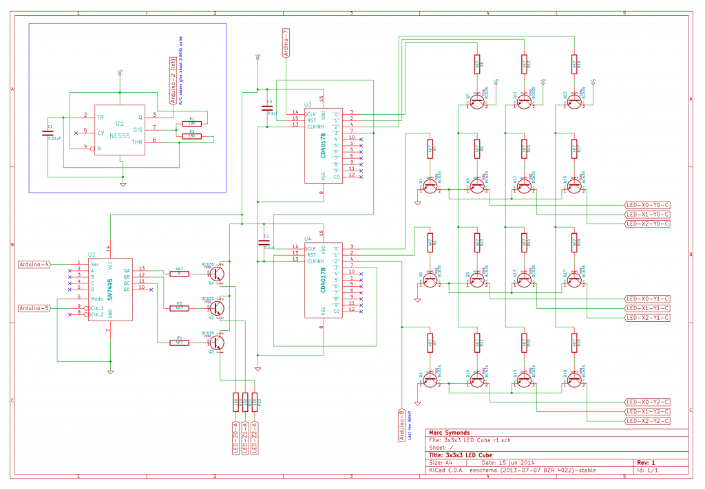
The first revision is a test of how I thought a larger LED cube could be made.
This version uses two 4017 decade counters to provide the X/Y scanning. These drive the transistors in the array which ground each column of 3 LEDs. The 4017's are slaved together; when the first one gets to the fourth row, it resets itself and then clocks the second 4017. When the second 4017 gets to the fourth row, it resets itself. Each 4017 drives three transistors (X and Y), which together then turn on one of the transistors in the 3×3 array.
The 555 timer is used to create a continuous pulse to the Arduino. This pulse is used to raise an interrupt. The interrupt calls the display routine which draws the next "column" of LEDs. The cube consitst of 9 "columns", and I wanted at least a 30fps display rate. I also wanted to have some sort brightness level; I decided on 8 levels. This meant I needed a pulse frequency of at least 30*9*8 = 2160 hertz. The capacitor and resistor values I used gave about 2.6KHz.
Revision 2
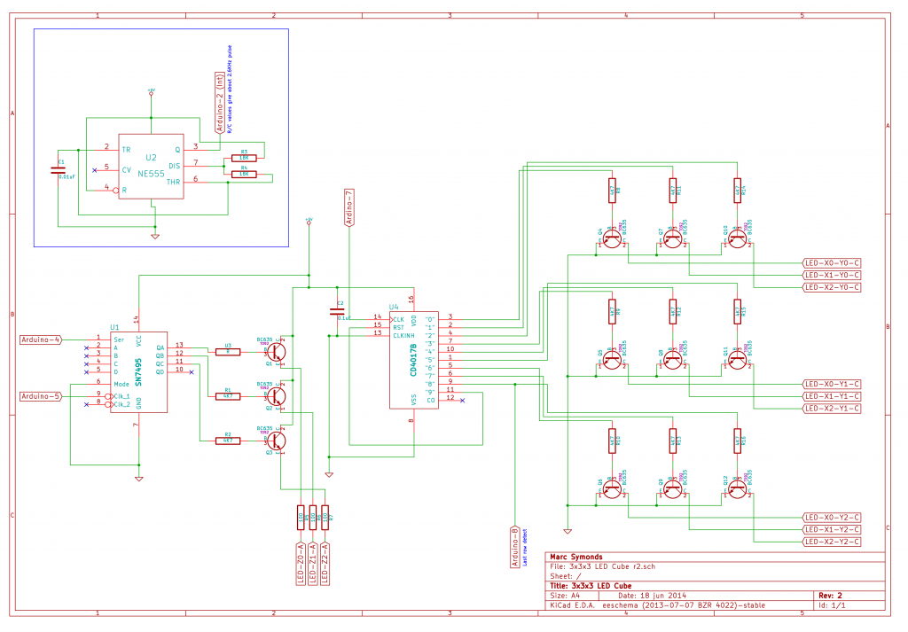
The first revision was a test of using the 4017s and an array of transistors to control a X/Y matrix. This second revision removes most of the unncessary components and just makes a 3x3x3 cube.
I got rid of one of the 4017s, and also the X/Y control transistor. The 4017 could directly drive the X/Y column transistors.
3x3x3 LED Cube r2 from Marc Symonds on Vimeo.
Revision 3
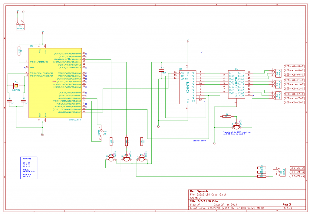
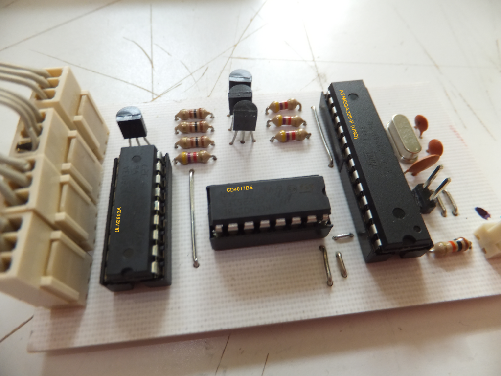
Removed some more unnecessary componants. I can get rid of the 555 and just use one of the PWM pins on the Arduino to provide the interrupt pulse. I can also get rid of the shift register and just use 3 pins from the Arudino directly. I can also replace 8 of the transistors in the 3×3 array with a ULN2803A, which is an 8 way Darlington array.
Finished 3x3x3 LED Cube in action using a home made PCB, except for the LEDs which are on a piece of stripboard.
3x3x3 Mono LED Cube r3 – On homemade PCB from Marc Symonds on Vimeo.
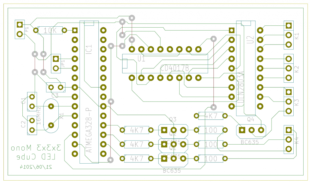
PCB Layout (component side):-
Completed PCB:-
int pin = 13;
volatile int state = LOW;
void setup()
{
pinMode(pin, OUTPUT);
attachInterrupt(0, blink, CHANGE);
}
void loop()
{
digitalWrite(pin, state);
}
void blink()
{
state = !state;
}
/* G.RAMASUBRAMANIAN PH:9042816495*/