I originally made my Word Clocks using PICAXE micro-controllers, some LED drivers, and plain, white, LEDs.
A while ago, I decided to upgrade them to colour LEDs; specifically the WS2812B type of LEDs which are serially addressable, and can be controlled directly from a micro-controller. I also changed the micro-controller to an Arduino. I originally built two of these clocks, and in the updated versions one is using an Arduino UNO, and the other an Arduino Nano – the same micro-controller, but in different formats.
The clock continuously, randomly, fades the colour of each word from one colour to another.
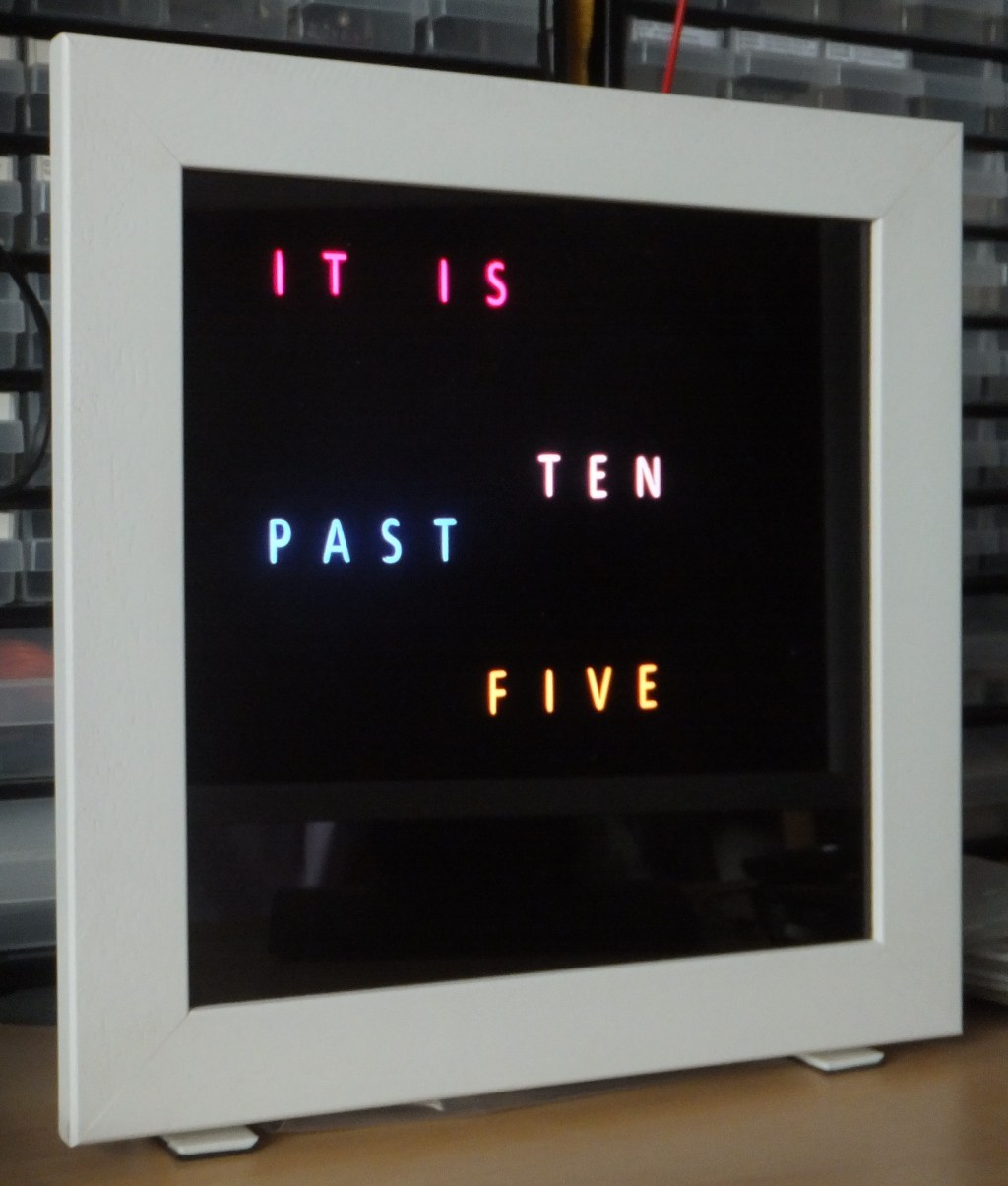
Word Clock in time mode
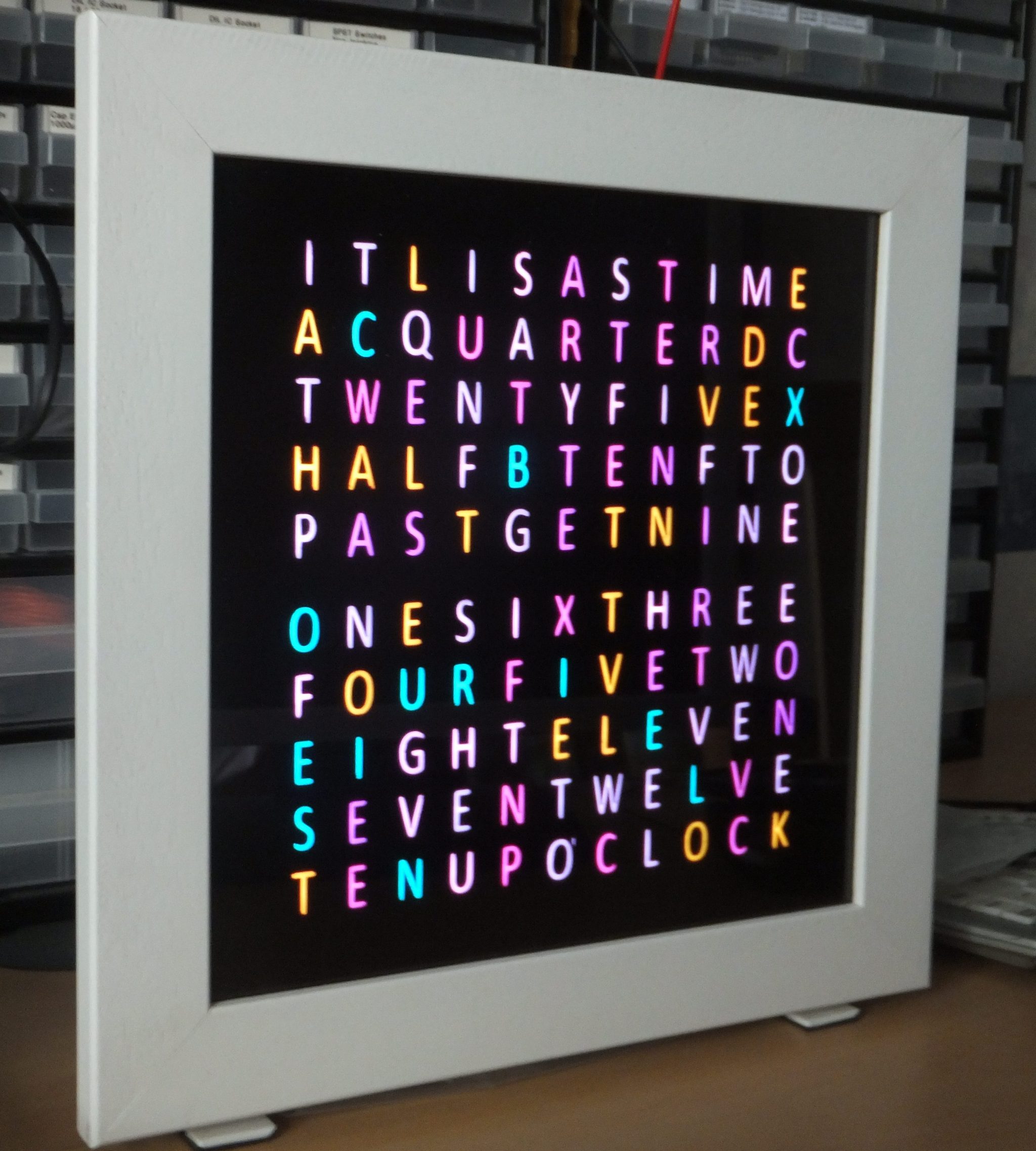
Word Clock in test mode
Recent Comments