Note, this relates to the Xbox One, and not the Xbox One X or Xbox Series X.

One day, the Xbox One decided it wouldn’t turn on. The PSU was plugged in and switched on, but there was no light on it. So I switched the PSU off at the mains, and switched it on again, where the orange light illumintated briefly before going out again. Nothing happened if I switched it off and on again, unless I waited a while after switching it off, then the orange light would come on again briefly.

Searching the internet, this seems to be a not uncommon problem, with the issue being 3 capacitors within the PSU which have blown. So I thought I’d have a look and see if I could repair it.

It should go without saying, but make sure the PSU is not
plugged in to the mains or Xbox before attempting this.

The PSU has 4 screws in the bottom beneath the 4 rubber feet. The rubber feet are actually attached to little plugs which plug the screw holes, rather than simply being glued down.

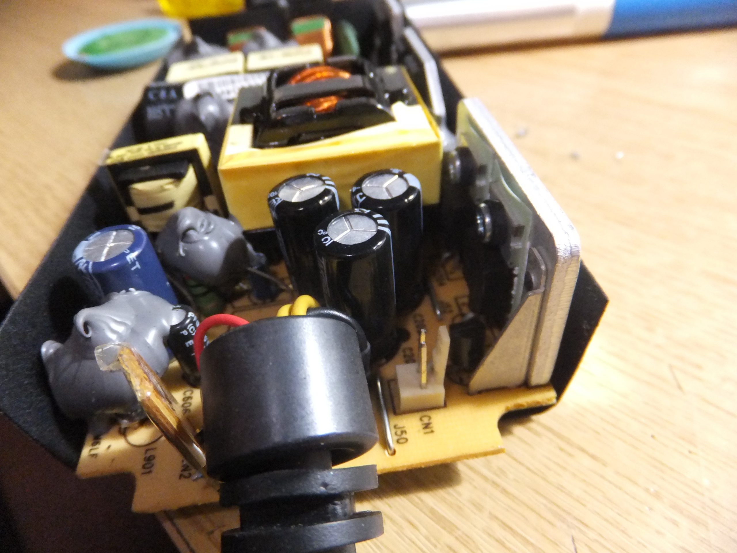
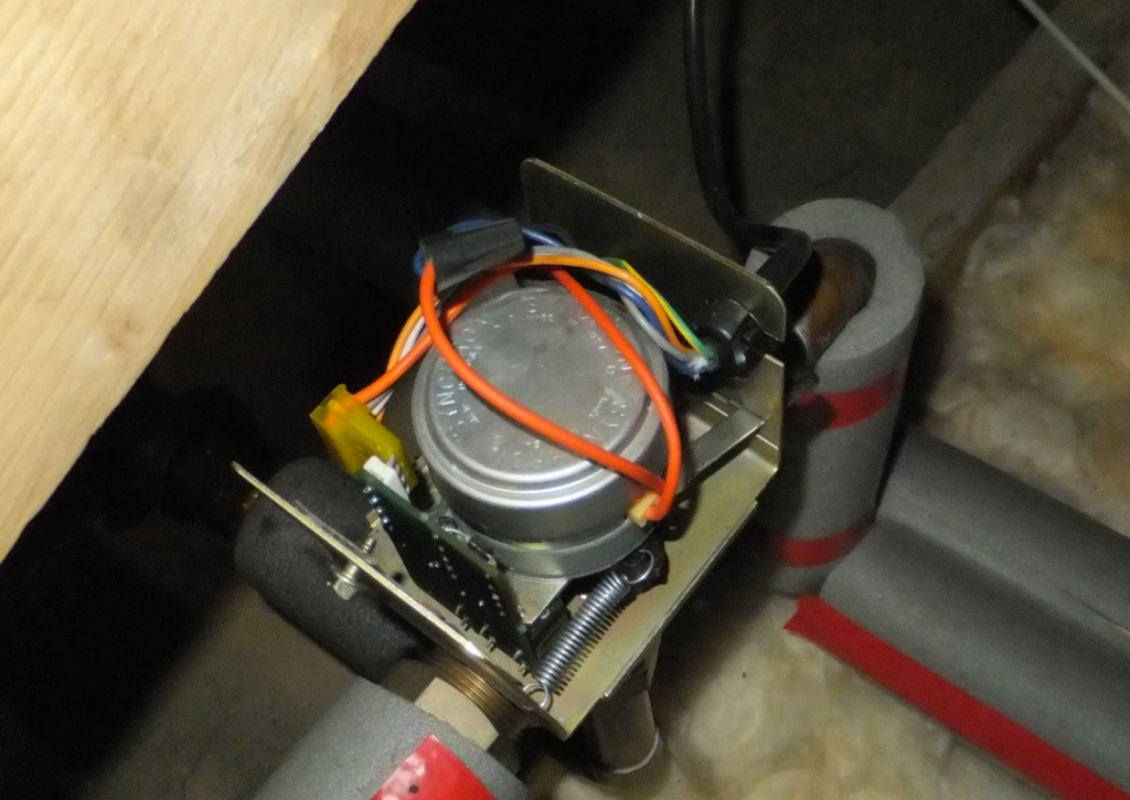
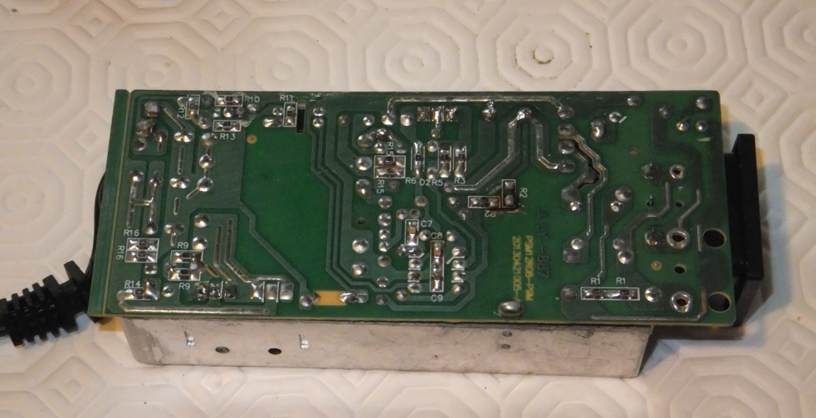
Once the screws are removed, the case easily comes apart in two halves, and you can extract the circuit board. One side of the board is hidden by a shield (which will need to be removed). On the visible component side, at the end where the lead to the XBox as located are 3 electrolitic capacitors. Here you can see that the tops of all 3 capacitors are pushed up (they would normally be flat):-

The 3 capacitors with the tops bowed outwards
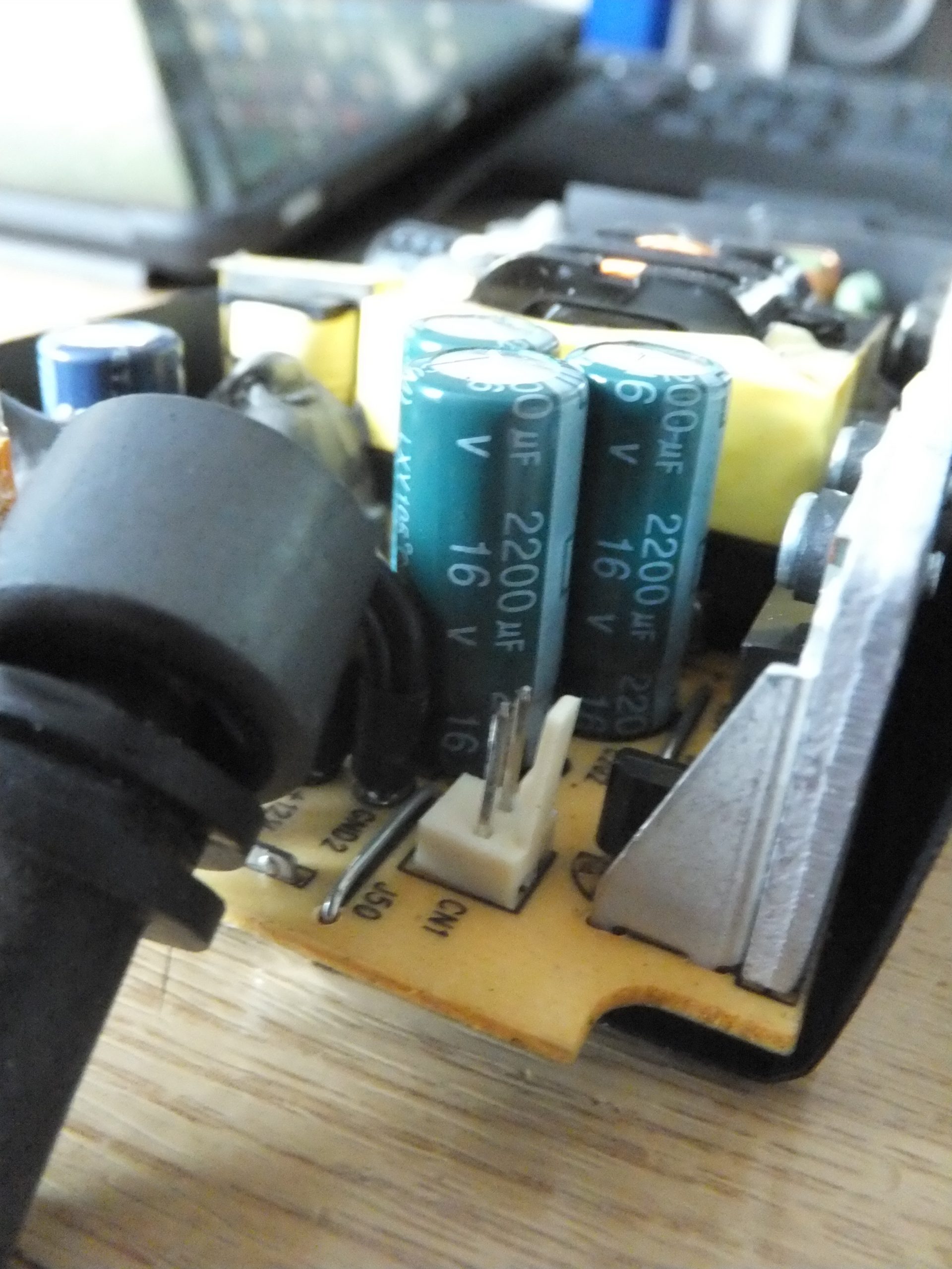
suggesting that they are blown

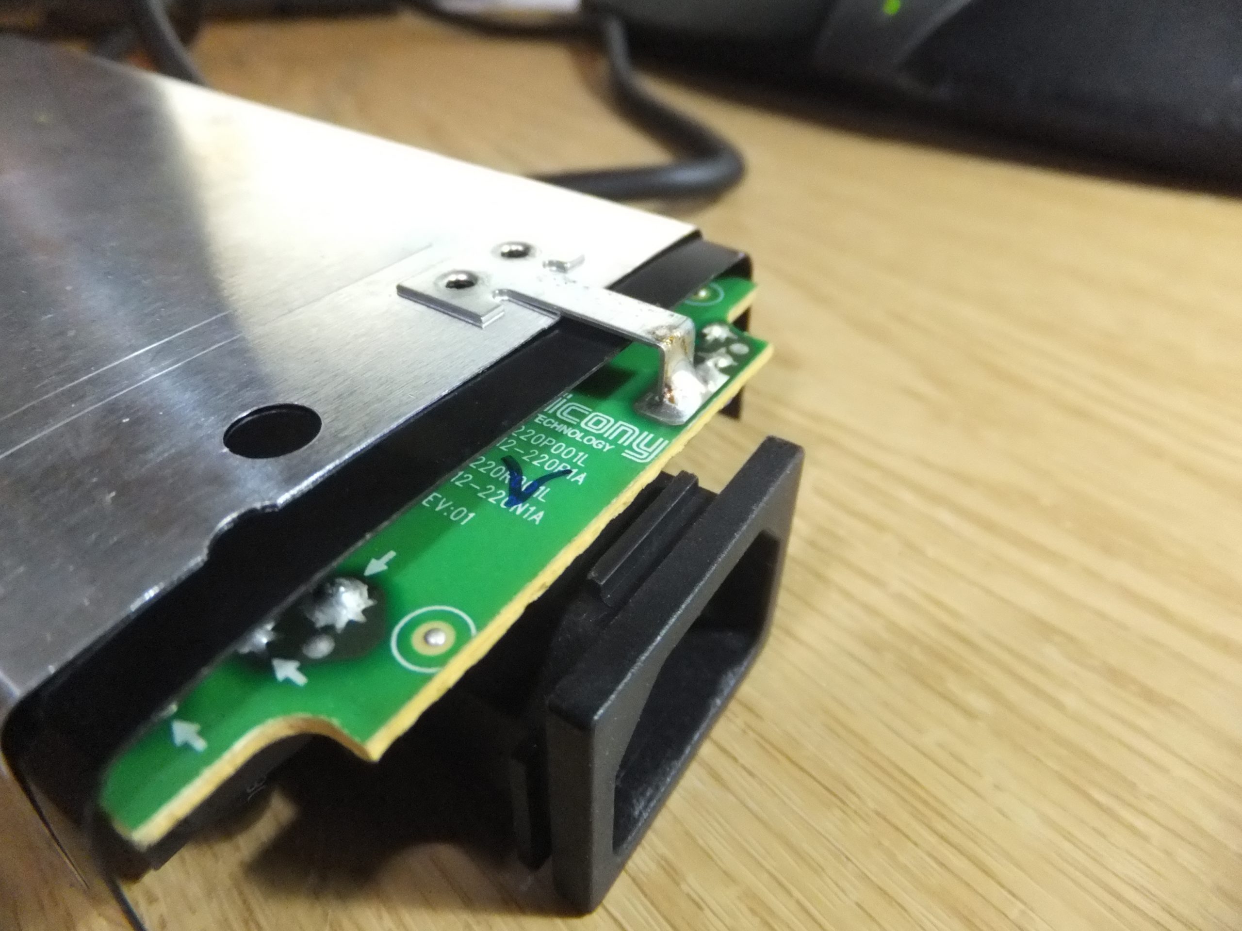
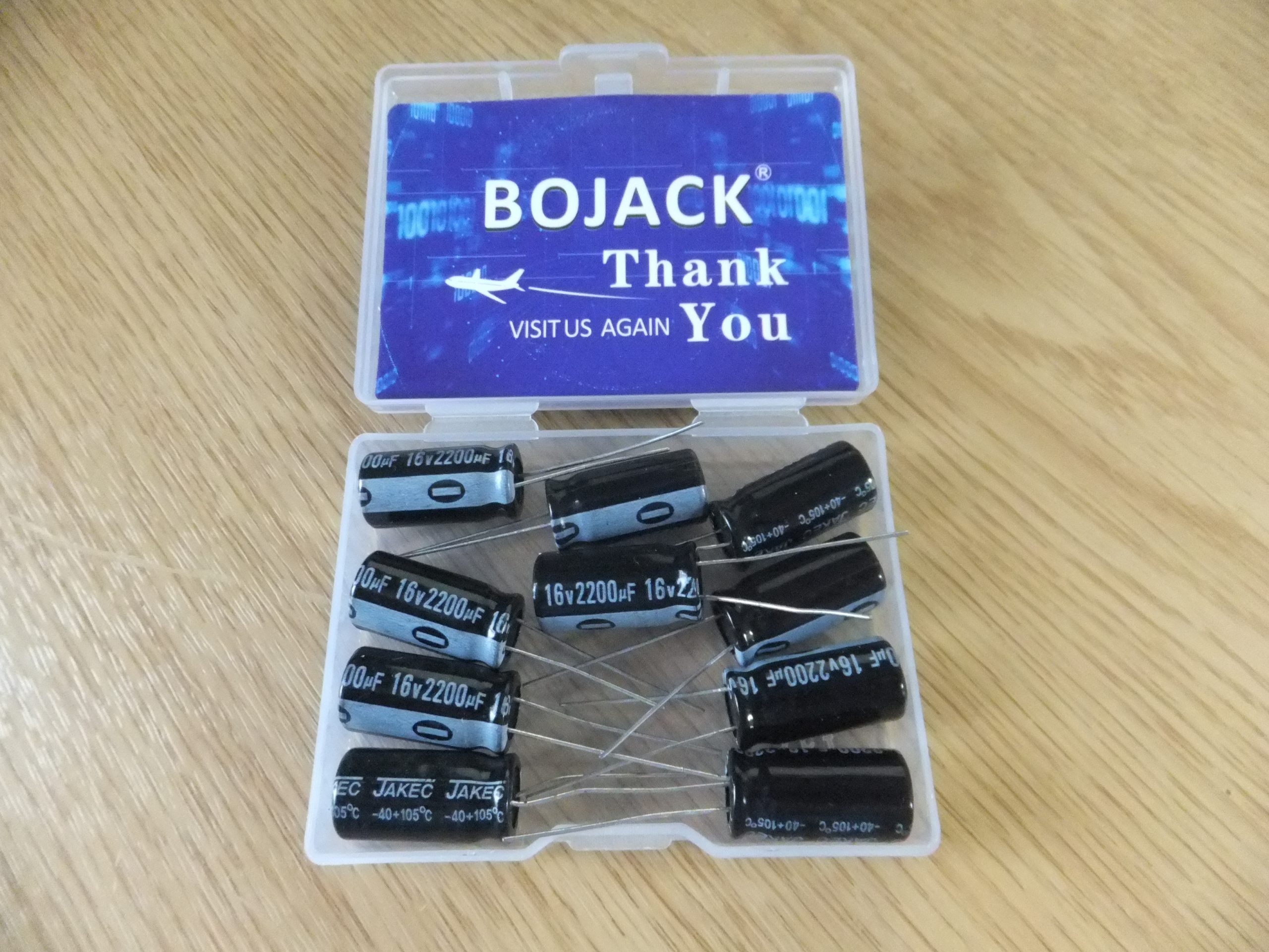
The 3 capacitors are all the same; 2200µF / 16v. To be able to the remove the capacitors, the shield on the other side of the board needs to be removed. The shield is simply soldered to the PCB in two places, and it is simply a matter of desoldering the shield at each point and pulling the shield off the board.

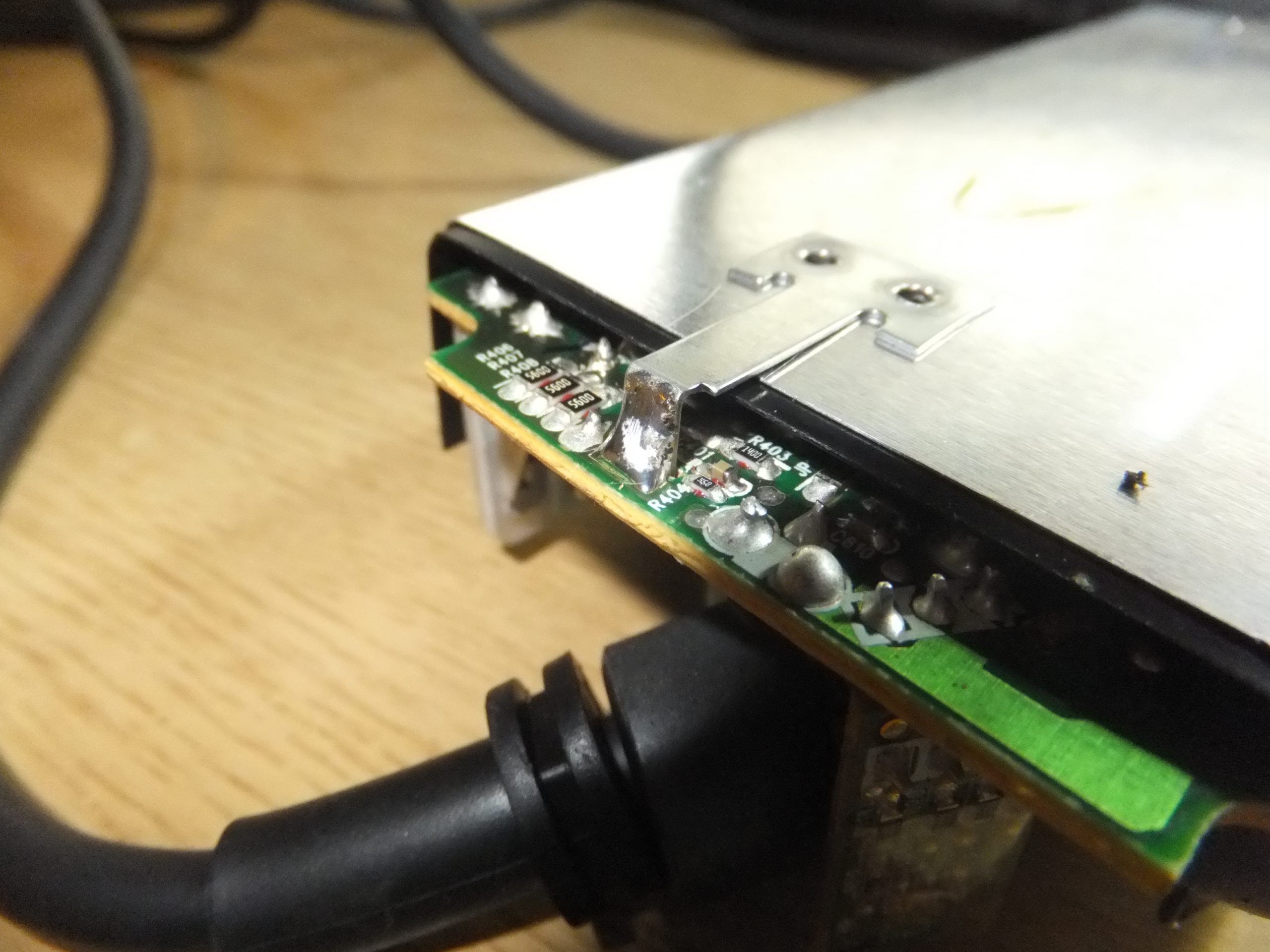
Once the shield has been removed, it is simply a matter of desoldering the 3 blown capacitors

Pads for the 3 capacitors highlighted in red.
The yellow highlight shows one of the holes for the tabs of the shield.

I simply desoldered the 3 capacitors, and replaced them with 3 new ones which I bought from Amazon, making sure that I got matching capacitors (2200µF / 16v), and also made sure that the ones I got would fit since they are quite close together on the board, so had to be no more then 10mm in diamter.

Capacitors from Amazon

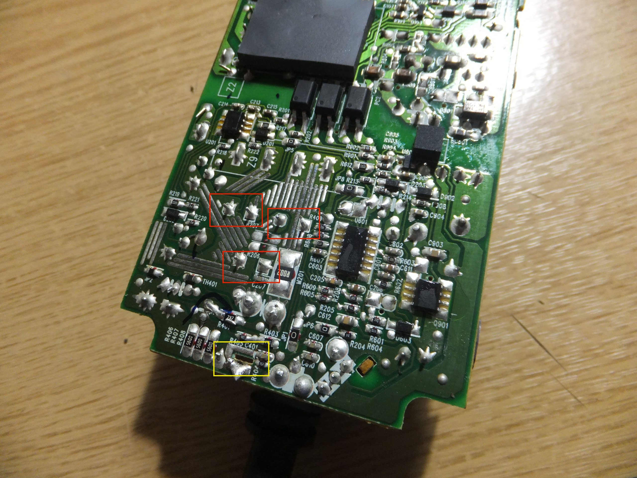
I simple soldered in the new capacitors, making sure that they are in the correct polarity. In the image below, the negative side for each of the capacitors is towards the heatsink on the right. Then I resoldered the shield, and put it all back together …

New capacitors installed.

… and we are back in business.

I originally made my Word Clocks using PICAXE micro-controllers, some LED drivers, and plain, white, LEDs.

A while ago, I decided to upgrade them to colour LEDs; specifically the WS2812B type of LEDs which are serially addressable, and can be controlled directly from a micro-controller. I also changed the micro-controller to an Arduino. I originally built two of these clocks, and in the updated versions one is using an Arduino UNO, and the other an Arduino Nano – the same micro-controller, but in different formats.

The clock continuously, randomly, fades the colour of each word from one colour to another.

Word Clock in time mode

Word Clock in test mode


My house phone has an LCD to show numbers and information, but some of the LC segments do not light up making the display useless:-

Display should say FREESTYLE

I thought there might be something wrong with the connection between the main board and the display, so I had a look. I was expecting a silicon zebra-stripe connector, which I've seen before, but this one uses a flexible connector that is heat bonded to the main board and the display. WARNING: be gentle with the flexible connector; it turns out the can tear quite easily frown.

I thought maybe the bonding between the connector and the board had deteriorated causing some of the connections to become disconnected. So I thought I'd try rebonding the connections by using my soldering iron. I set my iron to 200oC and slowly ran the tip along the connector where it is bonded to the board. After the first attempt I noticed some of the LCD segments were back, and after a few more goes, the display was back to normal:-

My second Android application.

I wrote this for use with a TK103A/B tracking device, which can determine its location using GPS or GSM and send the location to a mobile phone using SMS messaging.

The tracker can be used with the normal SMS messaging functions of your phone, but there isn't (that I was aware of) an application to go with it. You have to send a message to the Tracker, wait for the response and then click a link in the response to view the location on a map. You have to do this every time you want to get the tracker location.

So I decided to attempt to write an application that would allow you to request the tracker location via SMS, and when the response is received it will automatically extract the location and show it on a map.

Tracker Map Tracked item details

Source on GitHub.

TODO: If the tracker can't get GPS coordinates, it sends the GSM Location Area Code (LAC) and Cell ID (CID) of the tower it is connected to. It also sends its last known GPS coordinates. It would be nice to be able to lookup the LAC/CID coordinates, but I am not sure how to do that at the moment. There are some web sites with databases of this information, but I need to find out how I could access those. So for now, the application used the last known GPS coordinates.

11. March 2017 · Write a comment · Categories: Android · Tags: ,

My first attempt at an Android application; a Sudoku puzzle solver.

This was really just something to start learning Android development, and I didn't do this for any specific reason. It's been a learning experience, and I can appreciate more the work that goes in to developing applications for the platform with the various screen sizes, resolutions, pixel density.

This application simply lets you fill in the known numbers in a 9×9 Sudoku puzzle, and it will then attempt to solve the puzzle.

Source on GitHub.

This page is about how I managed to get the WordPress plugin WP-Mail-SMTP to send emails using my GMail account, which has 2 factor authentication enabled, using SSL/TLS.

… use them as decoration:-

cd-door

I used a multi-purpose impact adhesive to stick them to the door. Just required a few spots on each CD to stick them.

It's a lot easier to take the door off its hinges and lay it flat to do this. Leave the adhesive to dry for a few hours before re-hanging the door.

18. December 2014 · 3 comments · Categories: Home

I've had a problem with my heating/hot water system for a few months now. My system uses a 3 port valve to divert the hot water from the boiler to the hot water tank and/or the radiators. The problem is that the valve seemed to be stuck in the mid position, so it always sent the hot water from the boiler to both the hot water tank and radiators regardless of what I wanted – If I wanted hot water, I got heating as well, etc.

Since I have guests coming over Christmas, I thought I'd see if I can fix it.

The valve I have is a "Landis & Gyr" model MAV-322:-

01 - Valve cover

The valve isn't physically stuck, because I can manually force the actuator to move using the lever. Once you let it go though, it just returns to the middle position. So it must be electrical. The valve is pretty simple; there is a motor which turns the valve, and a small control board which has 5 resistors, a diode and two microswitches:-

WARNING – These valves use mains voltages inside – If you intend to dismantle one, make sure it is disconnected from the mains first.

02 - Valve electrics 03 - Control board 04 - Old microswitches

There are just two screws that hold in the motor and the plate to the valve. The circuit board is attached to the plate using two small screws which pass through the microswitches.

Not much to look at, so I tested the microswitches with a meter. The switches are Single Pole Double Throw (SPDT) types, with a normally closed (NC) connection and a normally open (NO) connection.

When I tested them I found that on both of the switches the NC connection didn't work, and on one of the switches the NO connection worked, and the other worked if you really pushed the plunger hard.


So after a quick search of the net for replacments, I found some on eBay (where else) for 99p each (plus £2.99 postage):-

05 - New microswitches

I simply unsoldered the two old switches, and soldered in the new ones. Put it all back together and now my system is working properly.


I opened one of the old switches to see why it wasn't working. Behold:-

06 - Corrosion

Very corroded. I suppose it's to be expected after 20 years of service.


Lorry vs Car from Marc Symonds on Vimeo.

Lorry clips back of car and spins it off the road.

M25 – 23/09/2014.

I bought a cheap 12V 6A PSU off of ebay last year which I use for powering projects that I’m messing around with. It’s appeared to be working fine until a few months ago when it stopped working.

So I cracked it open, as you do, and found that whoever/whatever soldered this thing did a pretty poor job. Many of the solder joings were dull, and the pins from a number of components, including the large capacitor and the devices connected to the heat sinks, had become unsoldered and were basically sitting in free air.

PSU Circuit Bottom PSU Circuit Top

So I resoldered everything and got it working again, and it’s been (apparently) fine since.


I have recently started playing with an electrec microphone with a view to using it with a MSGEQ7 graphic equaliser. I was breadboarding the microphone and simple transistor amplifier to feed in to the MSGEQ7 and was using my scope to view the wave forms, and noticed this continuous pulsing no matter what point in the circuit I tested

DS2_QuickPrint5

I thought at first it’s something caused by the DC filter capacitor, but I looked at other peoples circuits I didn’t notice this pulsing, so I tried replacing components, with no effect. I briefly thought it might be the scope picking up a 50Hz mains hum, but realised the pulse frequency is too high for that.

I then noticed that even when the scope probes aren’t touching my circuit, the pulse was still there, so I though there was something wrong with the scope. I turned off the PSU to power down my project while I tried to work out what was wrong with the scope, and noticed that the pulse went away. I turned the PSU back on and the pulse came back.


TL, DR

The PSU is somehow introducing some high frequency pulse in to something. I don’t know if it’s in to the mains line, or just some EMI – not really sure how to test either of these.


and A number of the componentsre was hardly any solder around a number of components, and both pins on the large capacitor were not soldered