I originally made my Word Clocks using PICAXE micro-controllers, some LED drivers, and plain, white, LEDs.

A while ago, I decided to upgrade them to colour LEDs; specifically the WS2812B type of LEDs which are serially addressable, and can be controlled directly from a micro-controller. I also changed the micro-controller to an Arduino. I originally built two of these clocks, and in the updated versions one is using an Arduino UNO, and the other an Arduino Nano – the same micro-controller, but in different formats.

The clock continuously, randomly, fades the colour of each word from one colour to another.

Word Clock in time mode

Word Clock in test mode


The next thing I thought I’d create was a box for the circuit board of the 3x3x3 LED cube. Seems like it should be easy (famous last words). Note to the people on YouTube who make Wings3D seem so simple and easy and can create a car in 20 minutes – I’m hating you right now.

After a few false starts, I finally managed to produce a box, and I even managed to include a hole in the side for a panel mount socket for powering the cube. I had originally planned to make a lid as well, but since it took me about 3 hours just to make the box, I decided to give the lid a miss.

Uneven

I also included some small pillars on the bottom that the circuit board can rest on. There’s a few extraneous edges in my model that I couldn’t get rid of – still a lot to learn with WIngs3D.


Printing the box took about 3 hours.

Printed Box


One thing that was concerning, the slicing program – ReplicatorG/Skeinforge (50) – produced a tool path the shook the printer a great deal. As it was printing the walls of the box, which are about 2mm thick, it did one layer length ways, and then the next layer crossways which creates a stronger bond between the layers. But when doing the printing crossways, because the travel was so short there was a lot of vibration as the print head went back and forth quickly. I think this vibration caused the glass plate on the print bed (which is held in place with some bulldog clips) to shift which meant the walls ended up being a bit wavy:-

Wavy

So I need to work out how to get the slicing program to produce a better tool path. Maybe slow the printhead down when doing short distances – don’t know if that’s possible.


Next thing was how to hold the board with the LEDs on to the box. If I’d thought about it earlier, I could have incorporated these into the box directly. I created some little brackets which fit over the wall of the box, and then hold the LED board.

PCB Clip

PCB Clip

PCB Clip

PCB Clip

I printed 4 of these. They only took a couple of minutes each.


Final result.

Boxed 333

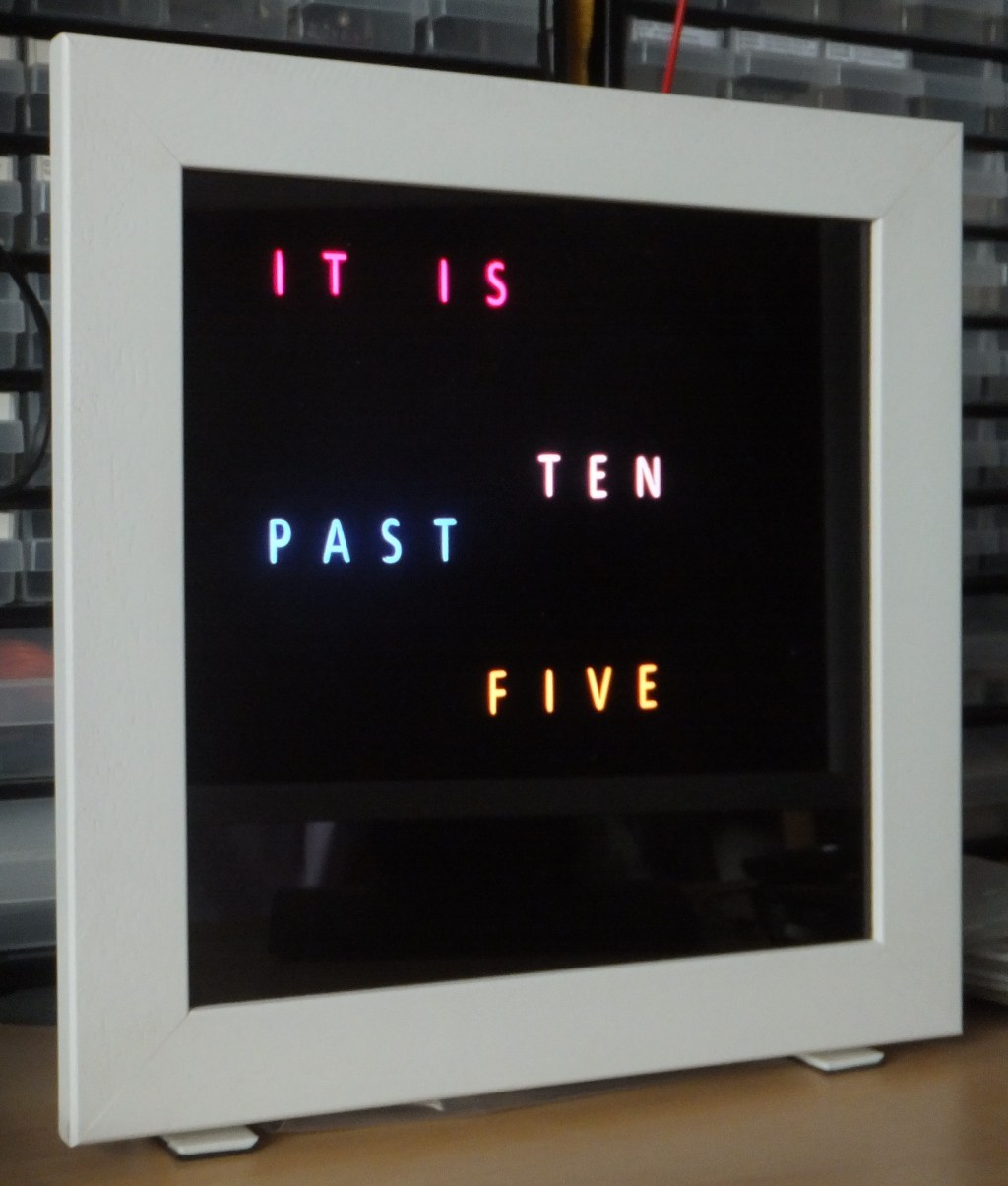
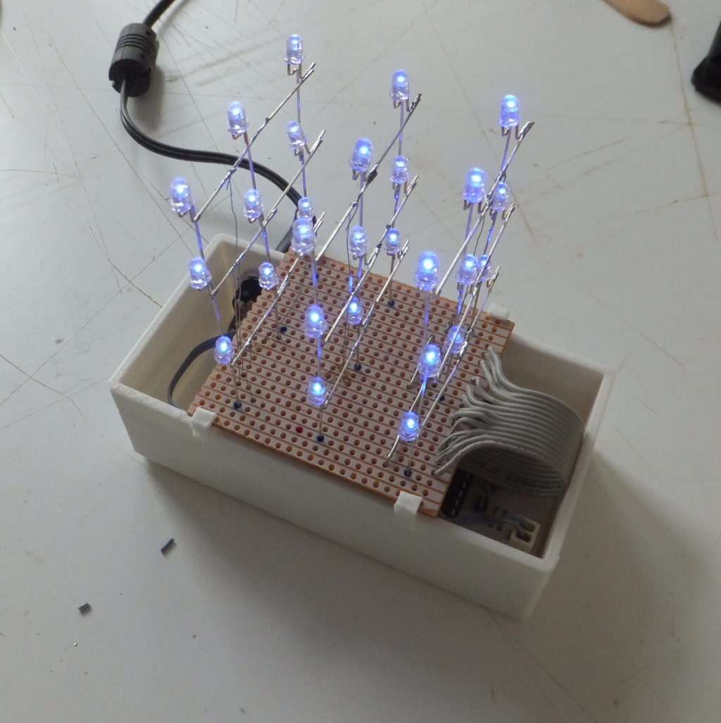
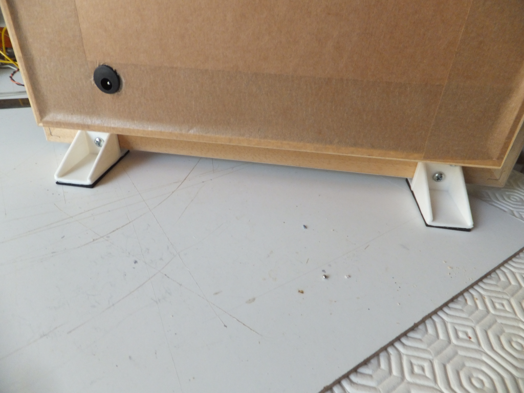
First thing I decided to have a go at designing and printing were some legs for my Word Clock.

I had already come across Wings3D when I downloaded KiCad for creating schemas and PCB layouts. I've never used Wings3D for designing anything, so this is going to be a learning excercise.

I worked out the design and measurements for the leg and went to design it in Wings3D. One thing I found alien was that WIngs3D has no concept of millimeters or inches or any term of measure, it just has units. The actual size of the object is just how you, or an external program, interprets those units. Not really sure what I was doing, I decided that 1 unit would be one centimeter – which actually turned out to be a stroke of genius later on.

Leg Wings3D

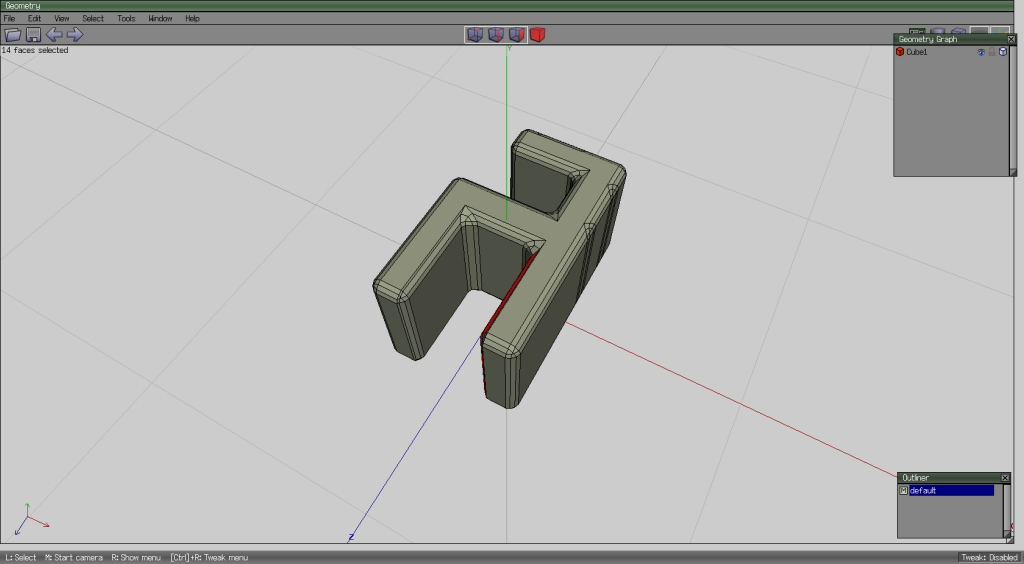
There are lots of extraneous verticies and edges in my model where I was playing around with Wings3D. I didn't really understand the principle extruding edges and faces out from an object, so this model is made from 4 shapes; one along the bottom, the upright and the two triangular supports. I also couldn't work out how to combine the objects in to one object; for example, the upright extends in to the bottom piece, I think this affected the way the final object was printed because you can see where the printer tried to print the faces that were imbedded within another object.

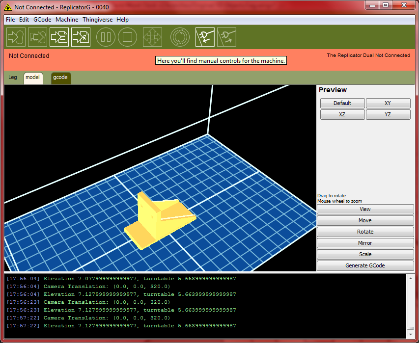
After completing my design, I exported the model to an stl file, and then imported that in to RelicatorG.

(Note regarding ReplicatorG: when I installed it, it needs to point to a Pyton interpreter. I had installed the latest Python 3.4, but I couldn't get ReplicatorG to recognise it, so I installed the earlier Python 2.6, which solved that problem.)

   Leg in ReplicatorG

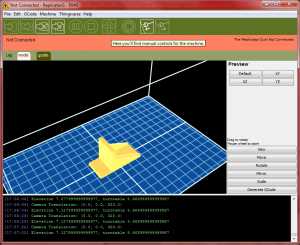
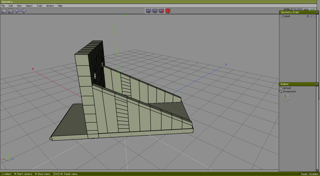
Once the file was loaded, the model appeared really tiny (smaller than in the image above). Doing some Googling, I discovered that the square grid in ReplicatorG represent centimeters, and the units used in Wings3D have been interpreted as millimeters; so I had designed my model as 5.4 units long (thinking 5.4 centimeters), and ReplicatorG has used that as millimeters – so my model was 5.4 millimeters long. A simple fix was to use the scale function to make the model 10 times bigger – and viola.

I didn't bother trying to play with the ReplicatorG settings and just left everything at the default and went straigt to printing the model.

Legs

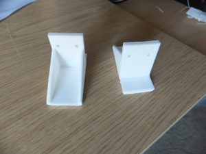
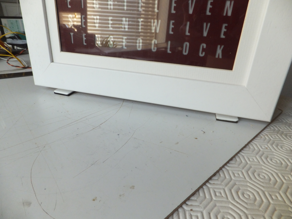
It took an hour to print each leg. The first leg printed out no problem, but half way through the first attempt at the second leg ReplicatorG seemed to freeze and it stopped printing. So I had to kill ReplicatorG, cancel the print on the printer and start again. It printed fine on the second attempt.

LegsF LegsB
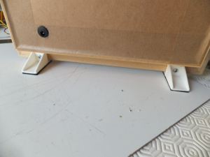
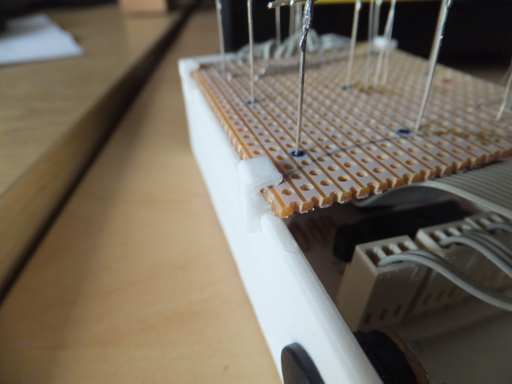
Pretty smart, if I say so myself.

23. July 2013 · Comments Off on New Pond · Categories: 3D Printing, Garden, Pond, Pond, Projects · Tags: ,

The pond in my garden is in a bit of a sorry state; it's leaking and it's in a bad location where it is difficult to get to most parts of it. It's also surrounded by bushes and trees and much of the debris from these end up in the pond. So I have decided to build a new pond with raised sides which will hopfully be easier to manage. Clicky

Current Pond