Note, this relates to the Xbox One, and not the Xbox One X or Xbox Series X.
One day, the Xbox One decided it wouldn’t turn on. The PSU was plugged in and switched on, but there was no light on it. So I switched the PSU off at the mains, and switched it on again, where the orange light illumintated briefly before going out again. Nothing happened if I switched it off and on again, unless I waited a while after switching it off, then the orange light would come on again briefly.
Searching the internet, this seems to be a not uncommon problem, with the issue being 3 capacitors within the PSU which have blown. So I thought I’d have a look and see if I could repair it.
It should go without saying, but make sure the PSU is not
plugged in to the mains or Xbox before attempting this.
The PSU has 4 screws in the bottom beneath the 4 rubber feet. The rubber feet are actually attached to little plugs which plug the screw holes, rather than simply being glued down.
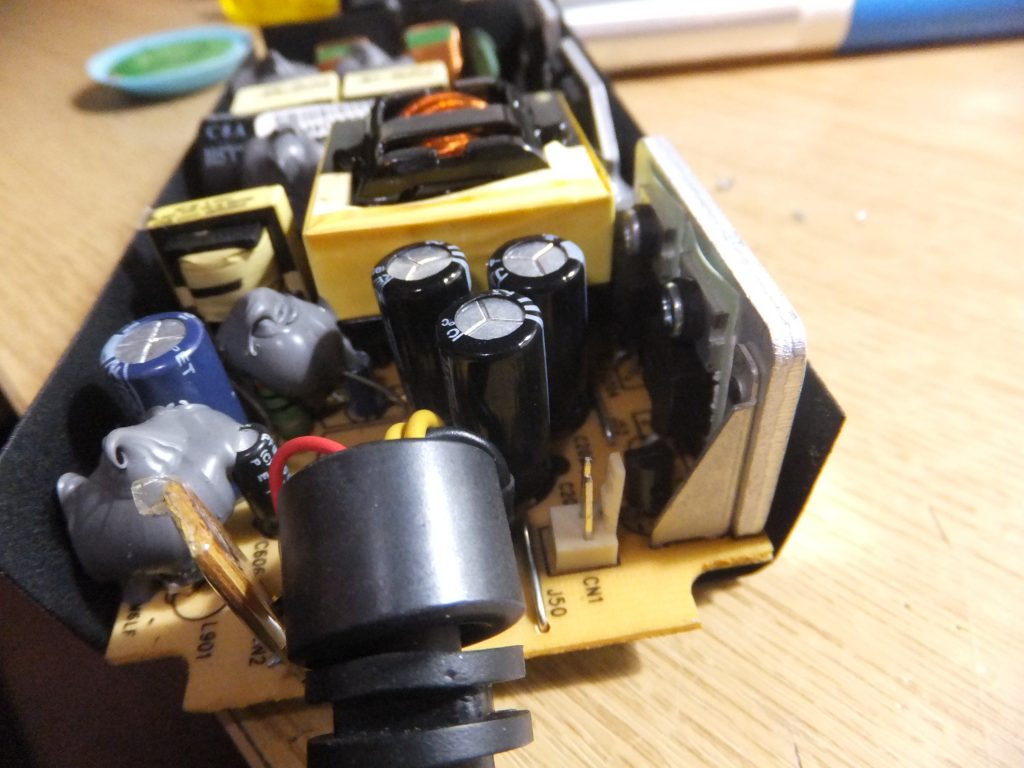
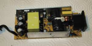
Once the screws are removed, the case easily comes apart in two halves, and you can extract the circuit board. One side of the board is hidden by a shield (which will need to be removed). On the visible component side, at the end where the lead to the XBox as located are 3 electrolitic capacitors. Here you can see that the tops of all 3 capacitors are pushed up (they would normally be flat):-
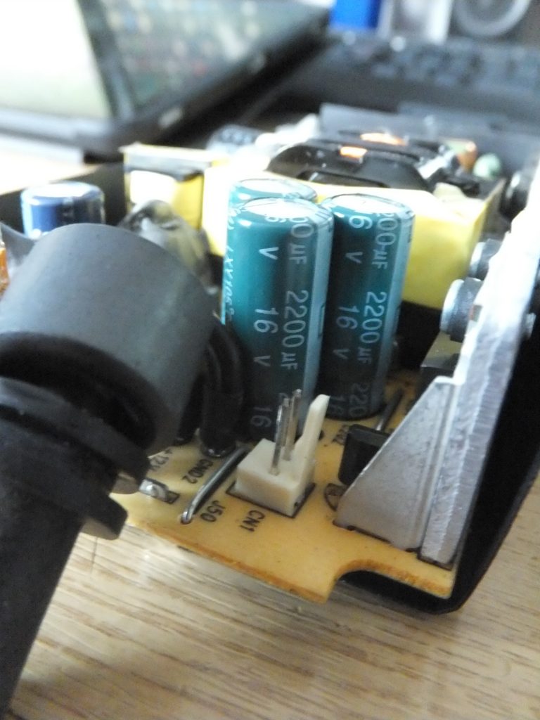
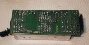
The 3 capacitors are all the same; 2200µF / 16v. To be able to the remove the capacitors, the shield on the other side of the board needs to be removed. The shield is simply soldered to the PCB in two places, and it is simply a matter of desoldering the shield at each point and pulling the shield off the board.
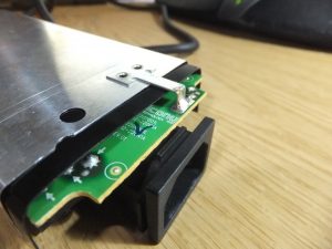
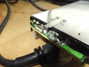
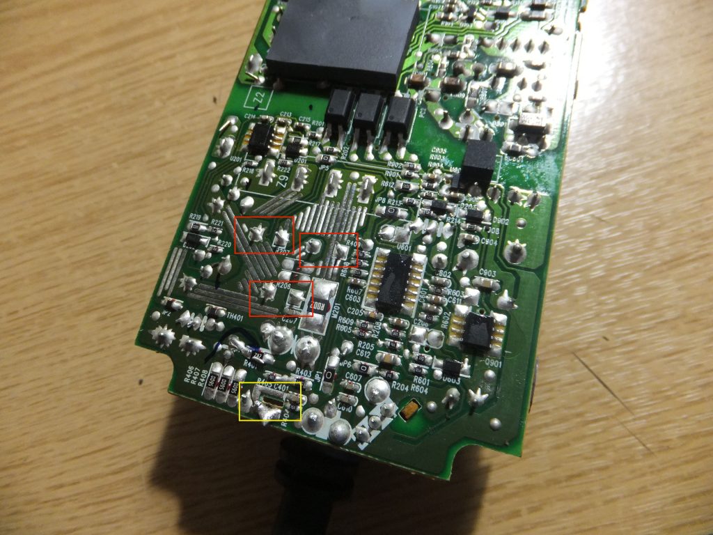
Once the shield has been removed, it is simply a matter of desoldering the 3 blown capacitors
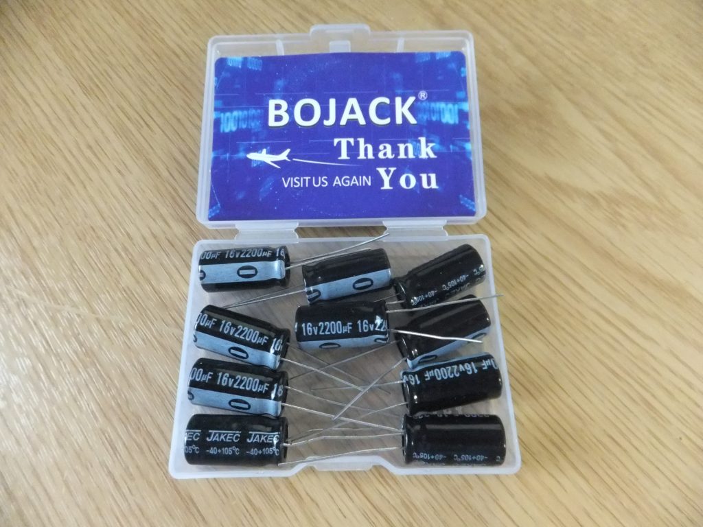
I simply desoldered the 3 capacitors, and replaced them with 3 new ones which I bought from Amazon, making sure that I got matching capacitors (2200µF / 16v), and also made sure that the ones I got would fit since they are quite close together on the board, so had to be no more then 10mm in diamter.
I simple soldered in the new capacitors, making sure that they are in the correct polarity. In the image below, the negative side for each of the capacitors is towards the heatsink on the right. Then I resoldered the shield, and put it all back together …
… and we are back in business.




Recent Comments