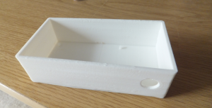
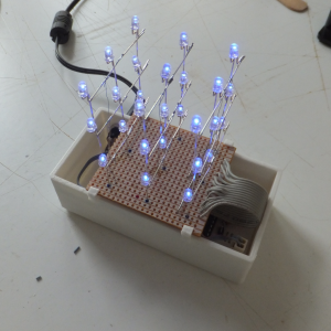
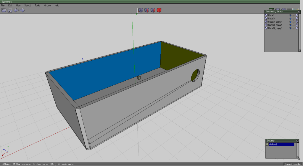
The next thing I thought I’d create was a box for the circuit board of the 3x3x3 LED cube. Seems like it should be easy (famous last words). Note to the people on YouTube who make Wings3D seem so simple and easy and can create a car in 20 minutes – I’m hating you right now.

After a few false starts, I finally managed to produce a box, and I even managed to include a hole in the side for a panel mount socket for powering the cube. I had originally planned to make a lid as well, but since it took me about 3 hours just to make the box, I decided to give the lid a miss.

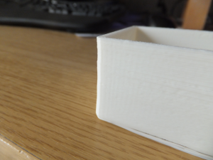
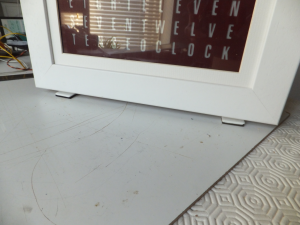
Uneven

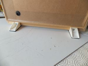
I also included some small pillars on the bottom that the circuit board can rest on. There’s a few extraneous edges in my model that I couldn’t get rid of – still a lot to learn with WIngs3D.


Printing the box took about 3 hours.

Printed Box


One thing that was concerning, the slicing program – ReplicatorG/Skeinforge (50) – produced a tool path the shook the printer a great deal. As it was printing the walls of the box, which are about 2mm thick, it did one layer length ways, and then the next layer crossways which creates a stronger bond between the layers. But when doing the printing crossways, because the travel was so short there was a lot of vibration as the print head went back and forth quickly. I think this vibration caused the glass plate on the print bed (which is held in place with some bulldog clips) to shift which meant the walls ended up being a bit wavy:-

Wavy

So I need to work out how to get the slicing program to produce a better tool path. Maybe slow the printhead down when doing short distances – don’t know if that’s possible.


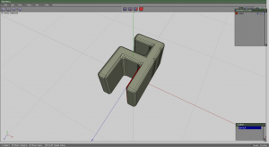
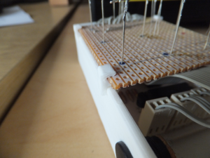
Next thing was how to hold the board with the LEDs on to the box. If I’d thought about it earlier, I could have incorporated these into the box directly. I created some little brackets which fit over the wall of the box, and then hold the LED board.

PCB Clip

PCB Clip

PCB Clip

PCB Clip

I printed 4 of these. They only took a couple of minutes each.


Final result.
Boxed 333

First thing I decided to have a go at designing and printing were some legs for my Word Clock.

I had already come across Wings3D when I downloaded KiCad for creating schemas and PCB layouts. I've never used Wings3D for designing anything, so this is going to be a learning excercise.

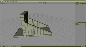
I worked out the design and measurements for the leg and went to design it in Wings3D. One thing I found alien was that WIngs3D has no concept of millimeters or inches or any term of measure, it just has units. The actual size of the object is just how you, or an external program, interprets those units. Not really sure what I was doing, I decided that 1 unit would be one centimeter – which actually turned out to be a stroke of genius later on.

Leg Wings3D

There are lots of extraneous verticies and edges in my model where I was playing around with Wings3D. I didn't really understand the principle extruding edges and faces out from an object, so this model is made from 4 shapes; one along the bottom, the upright and the two triangular supports. I also couldn't work out how to combine the objects in to one object; for example, the upright extends in to the bottom piece, I think this affected the way the final object was printed because you can see where the printer tried to print the faces that were imbedded within another object.

After completing my design, I exported the model to an stl file, and then imported that in to RelicatorG.

(Note regarding ReplicatorG: when I installed it, it needs to point to a Pyton interpreter. I had installed the latest Python 3.4, but I couldn't get ReplicatorG to recognise it, so I installed the earlier Python 2.6, which solved that problem.)

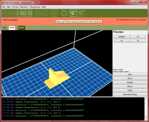
   Leg in ReplicatorG

Once the file was loaded, the model appeared really tiny (smaller than in the image above). Doing some Googling, I discovered that the square grid in ReplicatorG represent centimeters, and the units used in Wings3D have been interpreted as millimeters; so I had designed my model as 5.4 units long (thinking 5.4 centimeters), and ReplicatorG has used that as millimeters – so my model was 5.4 millimeters long. A simple fix was to use the scale function to make the model 10 times bigger – and viola.

I didn't bother trying to play with the ReplicatorG settings and just left everything at the default and went straigt to printing the model.

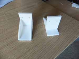
Legs

It took an hour to print each leg. The first leg printed out no problem, but half way through the first attempt at the second leg ReplicatorG seemed to freeze and it stopped printing. So I had to kill ReplicatorG, cancel the print on the printer and start again. It printed fine on the second attempt.

LegsF LegsB
Pretty smart, if I say so myself.

I decided to buy a 3D printer because I have some project ideas which I 3D printer might help with.

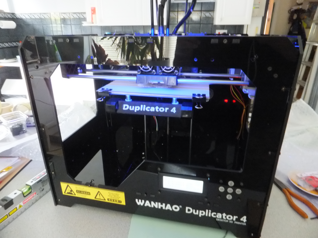
I went for a Wanhao Duplicator 4X as it seemed fairly reasonable and had some OK reviews. It has 2 extruders, which might mean you can print objects in two different colours and/or materials – I will have to test. It comes mostly pre-assembled; you have to fit the print head to the shuttle, a simple matter of two screws, fit the two reel holders on the back and fit the two fillament guides.

It also comes with 2 rolls of fillament – one ABS, the other PLA.

The main frame of the printer is made from 5mm perspex. It also comes with some side panels and a hood which you have to assemble. These are to stabilise the temperature within the printing area.

Wanhao Duplicator 4

I had an issue with the way everything was packed. The two reels of fillament were stored in two boxes placed inside the printer below the print bed, and the print bed had been lowered right down to hold them in place. It took a while to work out how to get those out of the printer without breaking anything. I didn't want to turn on the printer until I had taken all the packaging out, but in the end I had no choice. So I plugged it in and turned it on and found a Jog option within the menu which allowed me to raise the print bed and get the fillament reels out. This should have been in the instructions.


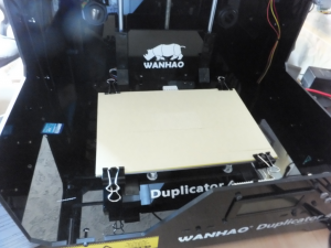
It also comes with a class plate to place over the heated print bed, and to cover the glass plate with some special heat resistant tape. The glass plate is held on the print bed with 4 supplied bulldog clips.

Glass Plate

One issue I had with this is that when the printing bed was raised up near the print head, and the print head moved to its home position (back, right), it caught the bulldog clip and pushed it off. Luckily it didn't damage the print head.


After putting the printer together, the first task is to adjust the print bead so that it is evenly spaced from the print head across the whole area. It does this by moving the print head to various points on the print bed and you have to adjust some screws under the bed to raise or lower it – You're supposed to just be able to slide a piece of A4 paper between the print nozzel and the bed. One minor issue I had was that when it moved the print head to the front of the print bed, the print head was positioned too far forward and was not over the print bed – so I had to do it by eye.


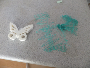
The printer also comes with a 2GB SD card which contains a couple of sample prints. Printing the sample using the PLA filament (white) worked fine, first time, but printing the sample using the ABS fillament (green) didn't quite work – They are both supposed to be butterflys.

Sample Prints

When printing the ABS sample, it seemed to be using the same temperature (220 for the head, 110 for the bed) as it did for the PLA fillament. Reading some posts about other people's experience with printing in these different materials, I am assuming the failure is down to the wrong temperatures being defined for the ABS sample print. So I will have to experiment with that.


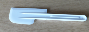
Also, one of these is quite useful for getting the printed model off of the print bed, because they stick pretty well:-

Plastic Knife

It's some sort of plastic knife or slicer – I don't really know. I happened to have one in the draw under the sink. It's been in the draw for ages, but I don't remember where it came from or how it got there – Probably fate.

After printing is complete it's a good idea to let the whole thing cool down for a bit because the model is still pretty flexible just after printing and trying to pry it from the print bed can mishappen it.


So far, so good.


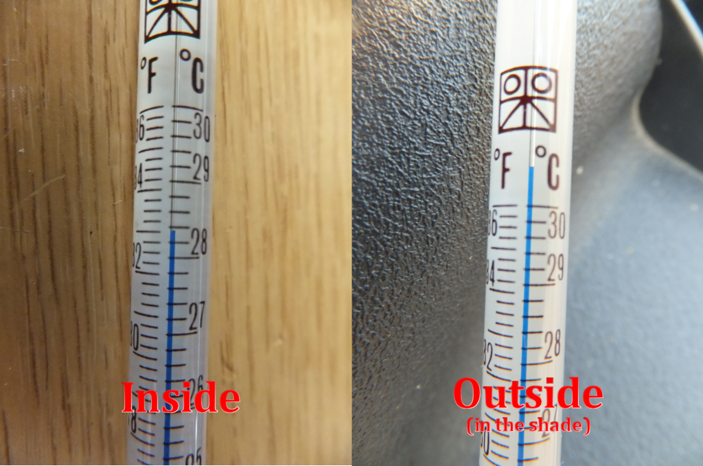
On the warm side

Had a go at creating a simple widget that displays pages related to the current page in the sidebar. WordPress has some pretty good documentation and there are plenty of examples around, so it was pretty simple:-

<?php
/*
Plugin Name: Show Related Pages
Description: Menu widget to show child pages of the current page.
Version: 0.1
Author: Marc Symonds
Date: July 2014
*/

class mss_showchildpageswidget extends WP_Widget
{
  // Constructor.
  
  function __construct()
  {
    parent::__construct(
        'mss_showchildpageswidget',
        'Show Child Pages',
        array('description' => 'Show child pages related to the current page')
      );
  }
  
  // Output front-end markup.
  
  public function widget($args, $instance)
  {
    global $post;

    // Only output something if viewing a page.
    
    if (is_singular() && $post->post_type == 'page')
    {
      // Get the ancestor pages for the current page.
      
      $elders = get_post_ancestors($post->ID);
      $ecount = count($elders);

      // The list we are going to build will contain the two most recent ancestors (parent and grandparent),
      // the current page with two levels of descendants (child and grandchild) and the siblings of the current
      // page with one level of descendant (child):-
      //
      // Grandparent
      //   Parent
      //     This page
      //       Child1
      //       Child2
      //         Grandchild1
      //     Sibling1
      //     Sibling2
      //       Child1
      // 

      $t = get_the_title($post->ID);
      $l = get_permalink($post->ID);

      $before_child = '<ul class="children"><li><a href="' . $l . '"><b>' . $t . '</b></a>';
      $after_child = '</li></ul>';

      $i = 2;
      $j = 0;
      while ($i > 0 && $j < $ecount)
      {
        $p = $elders[$j];
        $t = get_the_title($p);
        $l = get_permalink($p);
        
        $before_child = '<ul class="children"><li><a href="' . $l . '">' . $t . '</a>' . $before_child;
        $after_child = '</li></ul>' . $after_child;
        $i--;
        $j++;
      }

      // Get list of published pages that are children of the current page.

      $opts = array(
         'child_of'    => $post->ID,
         'depth'       => 2,
         'echo'        => 0,
         'post_type'   => 'page',
         'post_status' => 'publish',
         'show_date'   => '',
         'sort_column' => 'menu_order, post_title',
         'sort_order'  => '',
         'title_li'    => '', 
         'walker'      => '');

      $children = wp_list_pages($opts);
    
      // Get list of sibling pages of the current page.
      
      if ($ecount > 0)
      {
        $opts['child_of'] = $elders[0];
        $opts['depth'] = 2;
        $opts['exclude_tree'] = $post->ID;
        
        $siblings = wp_list_pages($opts);
      }
      else
        $siblings = '';

      // Output.
            
      echo $args['before_widget'];

      $t = $instance['title'];
      $t = apply_filters('widget_title', empty($t) ? 'Related Pages' : $t);

      if (! empty($t))
        echo $args['before_title'] . $t . $args['after_title'];

      echo $before_child;
      echo '<ul class="children">' . $children . '</ul>';
     
      echo $siblings;
         
      echo $after_child;      
        
      echo $args['after_widget'];     
    }
  }
} 


// Register my widget.

function mss_showchildpageswidget_load()
{
  register_widget('mss_showchildpageswidget');
}
add_action( 'widgets_init', 'mss_showchildpageswidget_load' );
?>

Thought I'd make another word clock with some imporvements. Clicky

[cough]I mean, damn butterflys,[/cough] flitting about, creating hurricans everywhere!!

Butterfly

Butterfly-take-off-sm

I was watching some videos about making PCBs using solder paste and ovens to reflow the solder, and I wondered how easy it would be to remove components in a similar fashion. What to use as the heat source?  A hot-air gun/paint stripper.

I had an old compact flash card reader that's been sitting in a draw for years, so I thought I'd use that as my first victim/experiment.

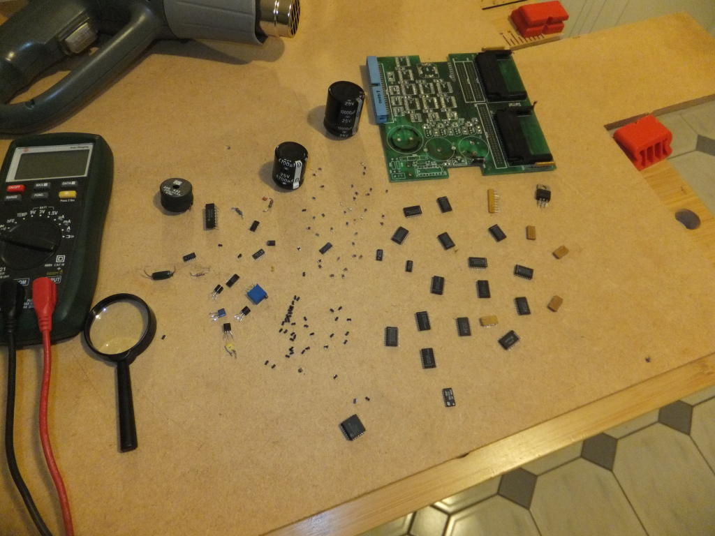
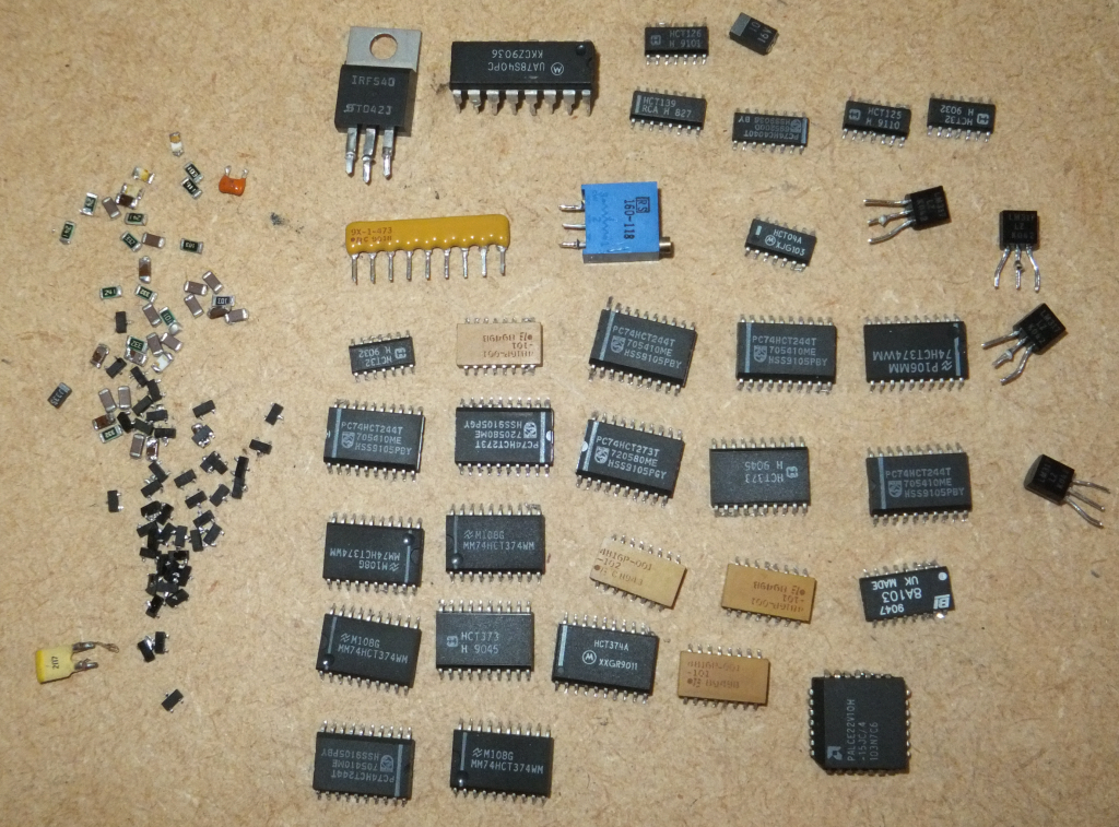
20 minutes later I have a bunch of random components, which may or may not be of some use at some point (Edit: I found a use for some of the SMD resistors in the other word clock I'm making), but hey – it worked:-

Components removed from PCB

Voila; a bunch of random components. There's some octal flip-flops, resistor arrays, SMD resistors, through-hole transistors, smd transistors and diodes, a couple of large capacitors and other bits and pieces.

Component Haul

The heat gun I have has two settings; I used the low setting, which is about 350 degrees C. The high setting is about 600 degrees.

I clamped the board upright in a vice and found that the larger SMD components just fell off as the solder melted, whereas the smaller components I had to pick off with some tweezers.

This particular board is a 4 layer board and I found that the through hole components took a minute or so of heating before the solder melted all the way through enough for me to pull the components off. I also tried this on an old PS/2 ball mouse PCB, which was just a double sided board, and the through-hole components on that came out much easier.

Only disappointing thing is that SMD capacitors don't have any markings on them, so you don't know what their capacitance is. How easy is it to make a capacitance meter?

This is a test using Windows Live Writer


DSCF0014

Storm cloud

Will it work?

24. June 2014 · 1 comment · Categories: Electronics · Tags:

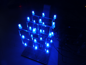
I thought I would have a go at making an LED cube.

I had some 4017 decade counters, so I was thinking about making a 10x10x10 RGB cube. From a numver of other LED cubes I've seen, the way that they do it is to provide power to all of the LEDs in every column that contains the LED to be lit, and then ground the plane containing the LEDs to be lit. If I wanted to have a 10x10x10 RGB cube, that would mean I would need 300 lines for the LED anodes, plus 10 for the cathods (assuming common-cathod LEDs).

It occurred to me that maybe you could do it another way; join all of the LED anodes together in a plane, and then ground each column. This way I would only need 30 lines for the anodes, plus 100 for the cathods.

I thought I would try a simple one first using this method; a 3x3x3 mono LED cube. I also thought I'd try some hardware that I haven't used before; an Arduino UNO.

3x3x3 Mono LED Cube

3x3x3